
Manufacturing method of enthalpy wheel humidifier

A manufacturing method, humidifier technology, applied in the direction of final product manufacturing, sustainable manufacturing/processing, electrochemical generators, etc., can solve the problems affecting the life of the humidifier, high friction resistance, reducing oxygen concentration, etc., to achieve replacement High wet heat transfer efficiency, simple manufacturing method, and the effect of ensuring oxygen concentration

Inactive Publication Date: 2013-04-03
SHANGHAI JIAO TONG UNIV
View PDF3 Cites 1 Cited by
  • Summary
  • Abstract
  • Description
  • Claims
  • Application Information

AI Technical Summary

Problems solved by technology

The patent retrieval of the prior art found that the authorized announcement numbers are CN 102013502A, CN 202019023U, and CN 202019024U patents all use enthalpy wheels made of ceramic materials, but the enthalpy wheels made of ceramic materials have the following problems: (1) The density of ceramics is high, Increase the system quality and the power consumption of the rotating motor, especially when it is used in automobiles, it is sensitive to weight and power consumption (efficiency); (2) The problem of ceramic wear is serious, and the wear between the ceramic enthalpy wheel and the housing will cause The increase of the gap between the enthalpy wheel and the housing will cause the exhaust gas of the fuel cell to be mixed into the fresh air, reducing the oxygen concentration in the intake air after humidification; The consumption and noise are large, which will affect the life of the humidifier
Due to these problems, ceramic enthalpy wheel humidifiers cannot well meet the high efficiency and long-term operation requirements of fuel cell systems

Method used

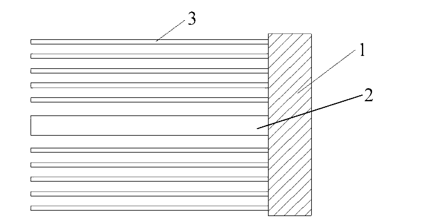
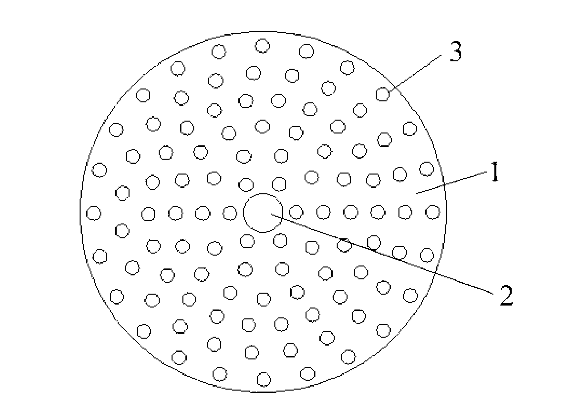
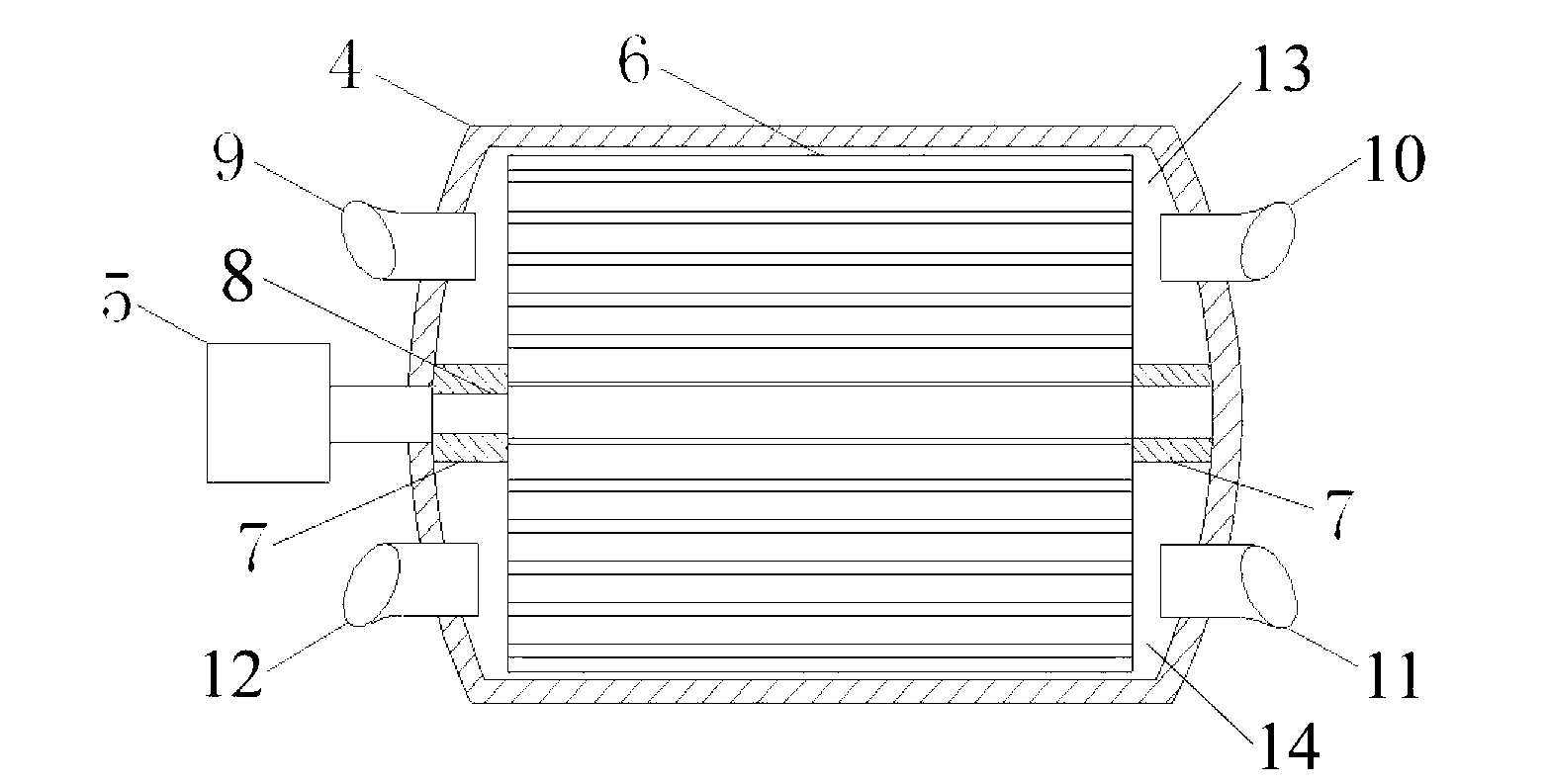

Image

  • Manufacturing method of enthalpy wheel humidifier
  • Manufacturing method of enthalpy wheel humidifier
  • Manufacturing method of enthalpy wheel humidifier

Examples


Embodiment 1

[0055] 1) Ingredients: According to the actual size of the enthalpy wheel in the enthalpy wheel humidifier, weigh various substances used. Based on the weight of the enthalpy wheel in the enthalpy wheel humidifier, weigh 4wt% aramid, 74wt% 5123 type phenolic resin, 7wt% urotropine and 15wt% ammonium bicarbonate.

[0056]2) Mixing: Put the weighed substances into a high-speed mixer, stir at a high speed to make the mixture even, and the stirring time is 1 minute.

[0057] 3) Heat treatment molding: put the mixture obtained after high-speed stirring into the mold and perform heat curing treatment. The heating temperature is set at 180°C, and the heating time is set at 60 minutes, then cooled and demoulded, and the obtained enthalpy wheel It is a porous honeycomb cylinder, and the through holes with a diameter of 5-10mm are uniformly distributed along the axial direction.

[0058] 4) Assembly: Put the enthalpy wheel into the cylindrical shell, the center of the enthalpy wheel sh...

Embodiment 2

[0061] 1) Ingredients: According to the actual size of the enthalpy wheel in the enthalpy wheel humidifier, weigh various substances used. Based on the weight of the enthalpy wheel in the enthalpy wheel humidifier, weigh 3wt% aramid fiber, 65wt% 5123 type phenolic resin, 6wt% urotropine and 26wt% ammonium bicarbonate.

[0062] 2) Mixing: Put the weighed substances into a high-speed mixer, stir at a high speed to make the mixture even, and the stirring time is 1 minute.

[0063] 3) Heat treatment molding: put the mixture obtained after high-speed stirring into the mold and perform heat curing treatment. The heating temperature is set at 180°C, and the heating time is set at 60 minutes, then cooled and demoulded, and the obtained enthalpy wheel It is a porous honeycomb cylinder, and the through holes with a diameter of 5-10mm are uniformly distributed along the axial direction.

[0064] 4) Assembly: Put the enthalpy wheel into the cylindrical shell, the center of the enthalpy w...

Embodiment 3

[0067] 1) Ingredients: According to the actual size of the enthalpy wheel in the enthalpy wheel humidifier, weigh various substances used. Based on the weight of the enthalpy wheel in the enthalpy wheel humidifier, weigh 3wt% aramid fiber, 57wt% 5123 type phenolic resin, 6wt% urotropine and 34wt% ammonium bicarbonate.

[0068] 2) Mixing: Put the weighed substances into a high-speed mixer, stir at a high speed to make the mixture even, and the stirring time is 1 minute.

[0069] 3) Heat treatment molding: put the mixture obtained after high-speed stirring into the mold and perform heat curing treatment. The heating temperature is set at 180°C, and the heating time is set at 60 minutes, then cooled and demoulded, and the obtained enthalpy wheel It is a porous honeycomb cylinder, and the through holes with a diameter of 5-10mm are uniformly distributed along the axial direction.

[0070] 4) Assembly: Put the enthalpy wheel into the cylindrical shell, the center of the enthalpy w...


PUM

PropertyMeasurementUnit
lengthaaaaaaaaaa
densityaaaaaaaaaa
densityaaaaaaaaaa

Abstract

The invention discloses a manufacturing method of an enthalpy wheel humidifier, which comprises the steps of putting aramid fibers, phenolic resin, pore former and curing agent into a high-speed mixer for high-speed mixing to obtain a uniform mixture, filling a mold with the mixture, putting the mold in an oven for thermocuring, conducting cooling and demolding, obtaining a porous cellular cylindrical enthalpy wheel, mounting the enthalpy wheel into a cylindrical housing, connecting to a motor through connecting shafts, and dividing the cylindrical housing into two areas with baffles. The invention further discloses the enthalpy wheel humidifier for a fuel cell, which comprises the cylindrical housing, the motor, the enthalpy wheel, the baffles and the connecting shafts. The enthalpy wheel humidifier can conduct air inflow heating and humidifying on the proton exchange membrane fuel cell more effectively, allows the proton exchange membrane fuel cell to exert performances better, and is simple in fabrication process, good in performance, lower in operating cost and long in service life.

Description

technical field [0001] The invention relates to a manufacturing method of a humidifier used in a fuel cell, in particular to a manufacturing method of an enthalpy wheel humidifier used in a proton exchange membrane fuel cell. Background technique [0002] A fuel cell is a clean, efficient, and long-life power generating device. Compared with conventional power generation technologies, fuel cells have great advantages in terms of efficiency, safety, reliability, flexibility, cleanliness, and operational performance, and their application prospects are very broad. As a kind of fuel cell, proton exchange membrane fuel cell also has the advantages of low operating temperature, high specific energy, long service life, fast response speed, and no electrolyte leakage. It has a good application prospect. During the operation of the proton exchange membrane fuel cell, the humidity control of the cathode intake air (air) is one of the most important links. On the one hand, if the a...

Claims


Application Information

Patent Timeline
Patent Type & Authority Applications(China)
IPC IPC(8): H01M8/04H01M8/04119
CPCY02E60/50Y02P70/50
Inventor 隋升苏凯华王曙中章俊良蒋峰景
Owner SHANGHAI JIAO TONG UNIV
Learn More