High-speed aluminum wire drawing machine

A wire drawing machine and high-speed technology, applied in the field of high-speed aluminum wire drawing machines, can solve the problems of inability to adjust the constant speed theory of traction and the wheel speed ratio of high-speed drawing towers, low wire drawing speed, reduced production efficiency and product applicability, etc. The effect of equipment manufacturing process, reducing intermediate drive shafts and improving wire drawing efficiency

Active Publication Date: 2013-04-10
HANGZHOU XINGGUAN MACHINERY
View PDF8 Cites 7 Cited by
  • Summary
  • Abstract
  • Description
  • Claims
  • Application Information

AI Technical Summary

Problems solved by technology

However, the current aluminum wire drawing machine has the following common technical problems in the design of the transmission structure: 1) The transmission structure is complex, through multiple sets of gear transmission, the noise is loud, the wire drawing speed is low, and the rotation of multiple shafts requires a certain amount of motor power, reducing The effective power of the aluminum wire drawing machine is reduced, which causes unnecessary waste for the user; 2) The transmission stability of the gear drive is poor after wear and tear, and the installation and maintenance requirements are high and the replacement is inconvenient; 3) Due to the use of sprocket drive (or gear transmission), cannot adjust the traction constant speed theory and the speed ratio of the high-speed wire drawing tower pulley, this design makes the drawing matching mold must be a set of matching molds for one outlet specification, and multiple sets of matching molds for multiple outlet specifications, which increases the The inventory of user moulds, which reduces production efficiency and product applicability

Method used


Image

  • High-speed aluminum wire drawing machine

Examples


Embodiment Construction

[0020] Below in conjunction with accompanying drawing, the present invention will be further described:

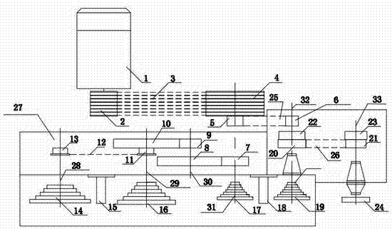
[0021] Such as figure 1 As shown, a high-speed aluminum wire drawing machine includes a frame 27 and a motor 1; on the frame 27, a low-speed guide wheel group 14, a low-speed mold frame 15, a low-speed tower wheel group 16, and a high-speed tower wheel group I17 are sequentially arranged. , high-speed mold frame 18, high-speed tower wheel group II19 and fixed speed wheel 24; Cooperate with setting low-speed mold group on the described low-speed mold frame 15, the number of low-speed molds on the low-speed mold group and the number of low-speed tower wheels on the low-speed tower wheel group 16 The number is the same, and the high-speed mold set is set on the high-speed mold frame 18. The number of high-speed molds on the high-speed mold set is consistent with the number of high-speed cone pulleys on the high-speed cone pulley group I17 and the high-speed cone pulley set II...


PUM


Abstract

The invention relates to a high-speed aluminum wire drawing machine, and belongs to the technical field of an aluminum wire drawing machine. The high-speed aluminum wire drawing machine comprises a rack and a motor, wherein a low-speed guide wheel set, a low-speed mould base, a low-speed cone pulley set, a high-speed cone pulley set I, a high-speed mould base, a high-speed cone pulley set II and a constant-speed wheel are sequentially arranged on the rack; the motor is connected with a driving pulley, the driving pulley is connected with a driven pulley, and the driven pulley is connected with the high-speed cone pulley set I; the high-speed cone pulley set I, the high-speed cone pulley set II and the constant-speed wheel are connected and transmitted through synchronous belts; the high-speed cone pulley set I is connected and transmitted with the low-speed cone pulley set through a gear; and the low-speed guide wheel set is connected with the low-speed cone pulley set in a chain transmission mode. With the adoption of the technology, the gear or chain transmission among the constant-speed wheel, the high-speed cone pulley set I and the high-speed cone pulley set II is changed into synchronous belt transmission. The high-speed aluminum wire drawing machine has the advantages of simple transmission structure design, high wire drawing speed, low energy consumption, good economic benefit, strong practicality, greatly reduced transmission noises and prolonged service life, and brings security assurance to the personal safety of operating personnel.

Description

technical field [0001] The invention belongs to the technical field of aluminum wire drawing machines, and specifically relates to a high-speed aluminum wire drawing machine with simple structure, low transmission noise, convenient speed adjustment, high efficiency, low energy consumption and strong practical applicability. Background technique [0002] At present, the transmission device of the high-speed aluminum wire drawing machine commonly used in production is usually driven by a power source motor through gear transmission to rotate multiple tower shafts and transition shafts, and power transmission is performed between each tower shaft through gears. However, the current aluminum wire drawing machine has the following common technical problems in the design of the transmission structure: 1) The transmission structure is complex, through multiple sets of gear transmission, the noise is large, the wire drawing speed is low, and the rotation of multiple shafts require...

Claims


Application Information

Patent Timeline
Patent Type & Authority Applications(China)
IPC IPC(8): B21C1/12
Inventor 袁关兴
Owner HANGZHOU XINGGUAN MACHINERY
Why Eureka
Try Eureka