

Recovery method for hydrogen sulfide gas in conveying process
A recovery method and technology in the transportation process, which is applied in the field of hydrogen sulfide, can solve the problems of non-reporting, misreporting or misreporting, and achieve the effects of reducing pollution, less one-time investment, and avoiding safety
Inactive Publication Date: 2013-04-10
WENGFU (GRP) CO LTD
View PDF4 Cites 0 Cited by
- Summary
- Abstract
- Description
- Claims
- Application Information
AI Technical Summary
Problems solved by technology
However, due to the influence of the accuracy of the detection instrument itself and the wind direction in the diffusion space, it may cause non-reporting, false reporting or false reporting
Method used
View moreImage
Smart ImageViewing Examples

Examples
Embodiment
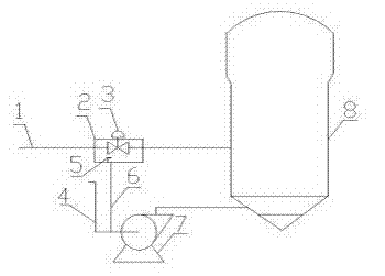
[0014] Take this method as an example in Wengfu Group Co., Ltd. 2×400,000 tons / year pyrite acid production plant: between the hydrogen sulfide pipeline 1 and the inlet pipe 4 of the roasting fan, connect the pipe 6 from the inlet pipe 4 of the roasting fan , add a sealing box 2 at the valve 3 and the place where it is easy to leak, introduce the pipeline from the inlet 4 of the roasting fan into the bottom of the valve 3 in the box of the sealing box 2 or the place where it is easy to leak, and place hydrogen sulfide at the mouth of the box in the box 2 Detector 5, sealing box 2 design inspection door, operating hand wheel is arranged outside sealing box 2.
Login to View More PUM
 Abstract
The invention discloses a recovery method for hydrogen sulfide gas in the conveying process after the hydrogen sulfide leaks. The method comprises the following steps: pipes (6) are guided out from a roasting fan inlet (4); sealing boxes (2) are additionally arranged at valves (3) and easy-leaking places; the pipes (6), guided out from the roasting fan inlet (4), are leaded under the valves (3) and the easy gas leaking places in box bodies of the sealing boxes (2); and hydrogen sulfide detectors (5) are placed in pipe openings of the box bodies of the sealing boxes (2). The method is simple, is low in one-time investment, improves the accuracy and the promptness of the hydrogen sulfide detectors, furthest protects the safety of polling staff, and reduces the environmental pollution after leakage.
Description
technical field [0001] The invention relates to hydrogen sulfide, in particular to a recovery method for accidentally leaking hydrogen sulfide tail gas during pipeline transportation in the coal chemical production process. Background technique [0002] In the process of coal chemical production, hydrogen sulfide cannot be discharged directly because it is highly toxic. The general method is to let it burn to generate sulfur dioxide, and then use the contact process to generate sulfuric acid. During pipeline transportation and before entering the combustion chamber, hydrogen sulfide will pass through the welding joints of the pipeline and valves and other places that are prone to leakage, especially the valves are prone to leakage due to the influence of many factors such as valve quality, construction quality, and aging of flange gaskets, resulting in Great security risk. In the existing practice, hydrogen sulfide detectors are generally installed at places prone to leaks....
Claims
Login to View More Application Information
Patent Timeline
 Patent Type & AuthorityApplications(China)
IPC IPC(8): F17D5/02
Inventor吕玉涛
OwnerWENGFU (GRP) CO LTD