
Composite surface flow wetland system

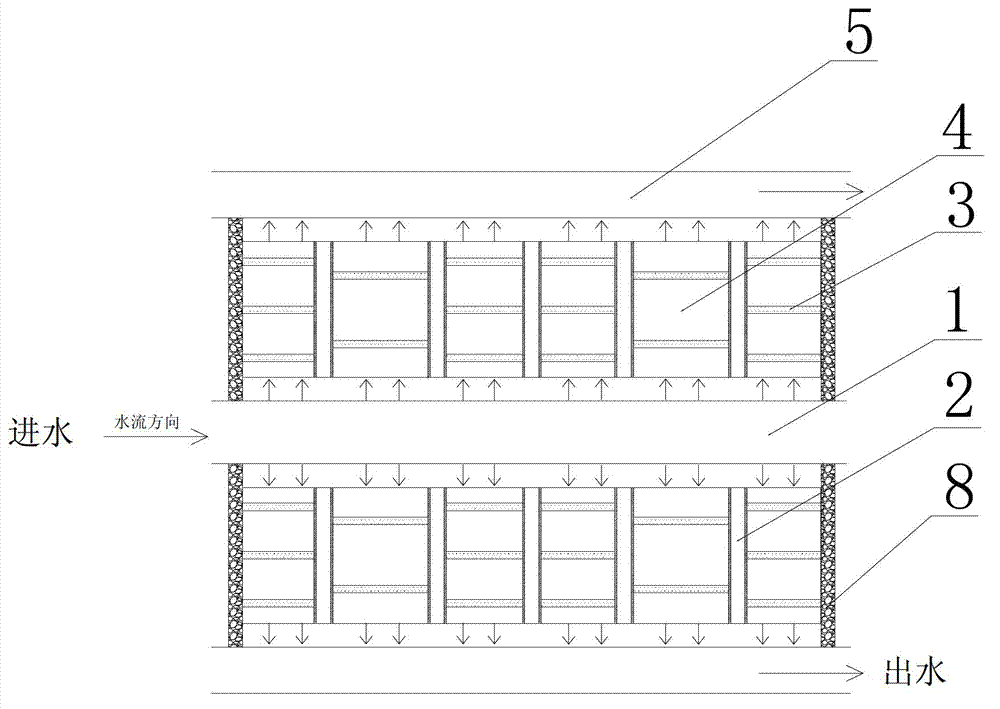
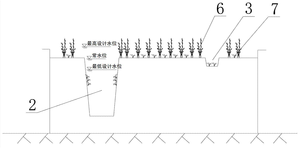
A compound and surface flow technology, applied in the field of environmental engineering, can solve the problems of reduced water purification capacity, large area occupied by water distribution, water delivery and water collection systems, and single habitat conditions, so as to enhance the conversion rate and improve water purification Ability, effect of guaranteeing survival

Active Publication Date: 2013-04-17
SHANGHAI INVESTIGATION DESIGN & RES INST
View PDF6 Cites 10 Cited by
  • Summary
  • Abstract
  • Description
  • Claims
  • Application Information

AI Technical Summary

Problems solved by technology

[0004] In the prior art, the general surface flow wetland base generates a uniform hydraulic load through topographical construction, and only emergent plants are planted. The plant configuration mainly focuses on screening plants with a single strong purification ability and organic combinations between different plants. Little consideration has been given to the construction of habitat diversity, different plant heights, sufficient and reasonable acceptance of solar radiation, and the enhancement of photosynthetic capacity per unit area, especially the simultaneous planting of emergent and submerged plants on the same planting base in wetland units. Configuration, water distribution, water delivery and water collection systems occupy a large area, and the actual effective use area and utilization efficiency of the wetland purification system are relatively low
To sum up, various surface flow wetlands now have obvious defects such as single habitat conditions, low effective use area of ​​wetland systems, insufficient consideration of plant three-dimensional configuration, etc., and the water purification ability of constructed wetlands will decrease after plants wither in winter. A Surface Flow Wetland System with Efficient Purification Effect

Method used


Image

  • Composite surface flow wetland system
  • Composite surface flow wetland system

Examples


Embodiment Construction

[0030] The implementation of the present invention will be illustrated by specific specific examples below, and those skilled in the art can easily understand other advantages and effects of the present invention from the contents disclosed in this specification.

[0031] see Figure 1 to Figure 2 . It should be noted that the structures, proportions, sizes, etc. shown in the drawings attached to this specification are only used to match the content disclosed in the specification, for those who are familiar with this technology to understand and read, and are not used to limit the implementation of the present invention. Limiting conditions, so there is no technical substantive meaning, any modification of structure, change of proportional relationship or adjustment of size, without affecting the effect and purpose of the present invention, should still fall within the scope of the present invention. The disclosed technical content must be within the scope covered. At the sa...


PUM


Abstract

The invention provides a composite surface flow wetland system, which comprises a water distribution channel used for water inflow, water collection channels positioned on the two sides of the water distribution channel and used for water discharge, and a plurality of deep grooves used for communicating the water distribution channel with the water collection channels, wherein the adjacent deep grooves are communicated through at least two shallow grooves to form a plurality of planting base cells; a mixed planting zone in the middle and emerged plant zones at the periphery of the mixed planting zone are arranged in each planting base cell; and emerged plants and submerged plants are interplanted in the mixed planting zones. Due to the stereoscopic plant configuration of the composite surface flow wetland system, the solar radiation can be effectively utilized, the plant photosynthesis in unit area can be improved, the habitat for growth can be enlarged, the redox capability of a wetland substrate can be improved, the purifying efficiency of the surface flow type artificial wetland can be improved, and the engineering construction and operation costs can be saved.

Description

technical field [0001] The invention relates to the technical field of environmental engineering, in particular to a composite surface flow wetland system based on bionics. Background technique [0002] At present, public water bodies such as lakes and rivers have been polluted to varying degrees. In order to ensure the safety of drinking water sources, it is necessary to improve the water quality of existing water sources through the construction of backup water sources or through purification projects, so as to avoid the growing water supply risks and eliminate or reduce them. The impact of water pollution incidents on the lives of residents. As a kind of purification project, constructed wetland can not only ensure the safety of drinking water sources, but also provide landscape effects. Through the adsorption and enhanced purification of the roots, stems, leaves and attached microorganisms of aquatic plants in the wetland, the adsorption and interception of water in the ...

Claims


Application Information

Patent Timeline
IPC IPC(8): C02F3/32
CPCY02W10/10Y02W10/37
Inventor 胡伟李巍朱雪诞陈煜权程南宁左倬俞士敏张俊郭萧冯太国
Owner SHANGHAI INVESTIGATION DESIGN & RES INST
Learn More