Non-isolated single-phase photovoltaic grid-connected inverter and on-off control timing sequence thereof

An inverter, non-isolated technology, applied in the field of high-efficiency grid-connected inverter topology, to achieve the effect of eliminating leakage current and small conduction loss

Active Publication Date: 2013-04-17
SOUTHEAST UNIV
View PDF8 Cites 18 Cited by
  • Summary
  • Abstract
  • Description
  • Claims
  • Application Information

AI Technical Summary

Problems solved by technology

So far, no solution has been proposed that achieves the best in both common-mode performance (leakage current elimination) and differential-mode performance (minimum conduction loss, highest efficiency)

Method used


Image

  • Non-isolated single-phase photovoltaic grid-connected inverter and on-off control timing sequence thereof
  • Non-isolated single-phase photovoltaic grid-connected inverter and on-off control timing sequence thereof
  • Non-isolated single-phase photovoltaic grid-connected inverter and on-off control timing sequence thereof

Examples


specific example

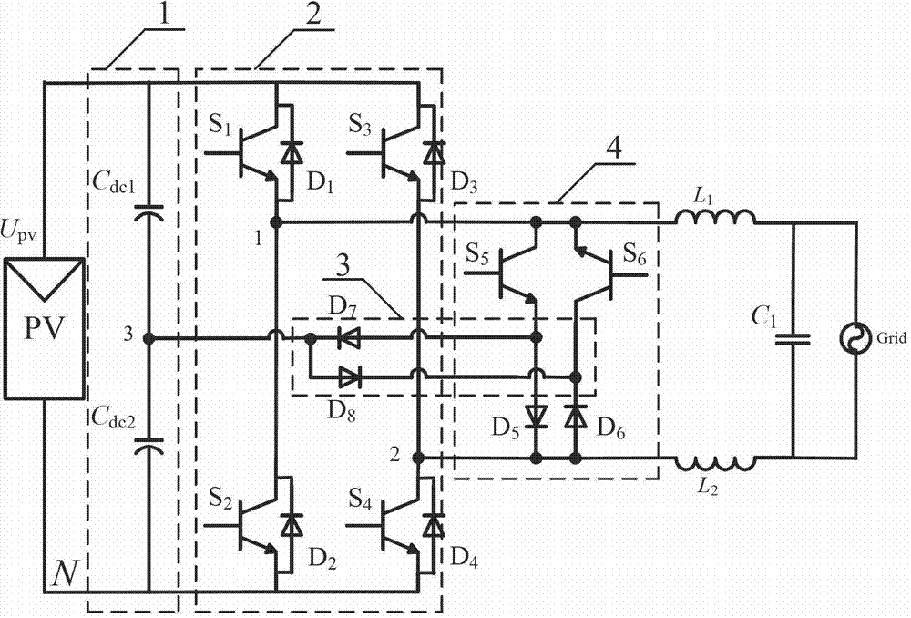
[0049] A specific example of the present invention is as follows: battery panel voltage U pv =400V, grid voltage U grid =220VRMS, grid frequency f grid =50Hz, rated power P N =5kW; DC bus capacitance C dc1 =C dc2 =470μF; filter inductance L 1 =L 2 =2mH; filter capacitor C 1 =6μF; the parasitic capacitance C of the battery board to the ground pv1 =C pv2 =0.15μF; switching frequency f=20kHZ.

[0050] Figure 6a and Figure 6b It is the specific working waveform diagram of this example. From Figure 6, we can see the grid voltage and grid current i in a grid cycle g And differential mode, common mode voltage waveform diagram. It can be seen that the differential mode voltage v DM , common mode voltage v CM Consistent with the principle analysis, except for the voltage spike caused by the switching action, the common-mode voltage is a constant value.

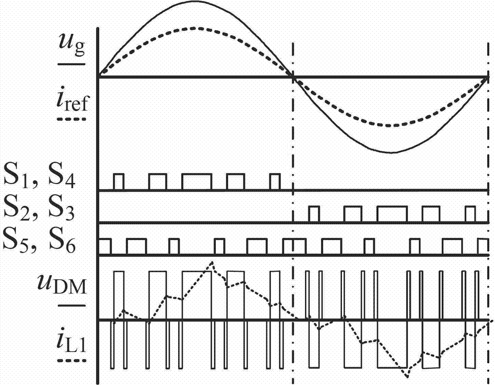
[0051] Figure 7a and Figure 7b They are the waveform diagrams of the switch drive signal, the inductor current ...


PUM


Abstract

The invention provides a non-isolated single-phase photovoltaic grid-connected inverter which is low in conduction loss and leakage current, and an on-off control timing sequence of the non-isolated single-phase photovoltaic grid-connected inverter. The photovoltaic grid-connected inverter comprises a voltage-dividing capacitor branch (1), a full-bridge basic unit (2), a clamping branch (3) and a follow current branch, which are connected with each other. According to the non-isolated single-phase photovoltaic grid-connected inverter and the on-off control timing sequence thereof disclosed by the invention, two controllable switch tubes and two diodes are additionally arranged on the basis of the single-phase full-bridge inverter circuit respectively to form a zero-level flow current branch; two diodes and a voltage-dividing capacitor are additionally arranged in the zero-level flow current branch to form a dual-direction clamping branch; the dual-direction clamping branch is matched with the on-off timing sequence to realize that common-mode voltage is the same constant voltage value at a power transmission stage, a dead zone stage and a flow current stage, so that leakage current of the non-isolated grid-connected inverter is removed. Moreover, the output current is enabled to only flow through two power tubes at the power transmission stage and the flow current stage, so that the conduction loss is the lowest.

Description

technical field [0001] The invention relates to a non-isolated photovoltaic grid-connected inverter and its switch control sequence, belonging to the technical field of high-efficiency grid-connected inverter topology. Background technique [0002] Non-isolated photovoltaic grid-connected inverters have the advantages of high efficiency, small size, light weight and low cost. However, due to the existence of the parasitic capacitance of the solar panel to the ground, the switching action of the switching device of the grid-connected inverter may generate a high-frequency time-varying voltage to act on the parasitic capacitance, and the leakage current induced by this may exceed the allowable range. The generation of high-frequency leakage current will bring conduction and radiation interference, increase the harmonics and loss of the incoming current, and even endanger the safety of equipment and personnel. [0003] The bipolar SPWM full-bridge grid-connected inverter can e...

Claims


Application Information

Patent Timeline
IPC IPC(8): H02M7/537
CPCY02E10/56
Inventor 肖华锋
Owner SOUTHEAST UNIV
Why Eureka
Try Eureka