
Mixing barrel with adjustable radiation effect

A heat dissipation effect and mixing tank technology, applied in the direction of mixer accessories, dissolving, mixing machines, etc., can solve the problems of poor safety, poor versatility, and poor structure compactness, and achieve the effects of good versatility, light weight, and reduced inertia

Inactive Publication Date: 2013-04-24
ZHEJIANG MARINE DEV RES INST
View PDF6 Cites 4 Cited by
  • Summary
  • Abstract
  • Description
  • Claims
  • Application Information

AI Technical Summary

Problems solved by technology

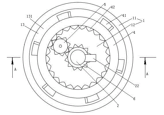
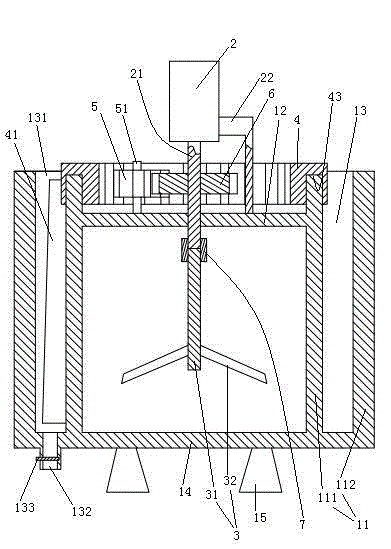
[0005] The first object of the present invention is to provide a mixing tank with adjustable heat dissipation effect that can easily change the heat dissipation effect of the tank according to needs, which solves the problem that the existing mixing tank can only be in the state of heat insulation or heat conduction. The problem of poor versatility
[0006] The second object of the present invention is to provide a stirring tank with light weight, compact structure and adjustable cooling effect without external impellers for heat dissipation. Problems of poor structural compactness and poor safety caused by heat dissipation of the impeller

Method used


Image

  • Mixing barrel with adjustable radiation effect
  • Mixing barrel with adjustable radiation effect
  • Mixing barrel with adjustable radiation effect

Examples


Embodiment 2

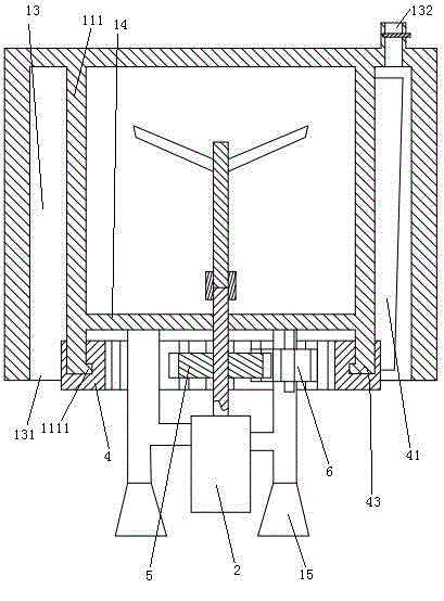
[0029] Embodiment two, see image 3 , The difference with the first embodiment is: the stirring motor 2, the driving gear 6 and the intermediate gear 5 are all arranged on the lower end wall 14 of the barrel 1, and the stirring motor 2 is fixed on the supporting feet 15. A lower end of the inner wall 111 is provided with an inner flange 1111 . The section of the chute 43 is "L" shape. The driving ring 4 is suspended and slidably connected to the lower end of the inner side wall 111 through the inner flange 1111 and the chute 43 . The air outlet 131 is formed by completely opening the lower end of the cavity 13 . The air inlet 132 is provided on the upper end of the cavity 13 .

Embodiment 3

[0030] Embodiment three, see Figure 4 , the difference with the first embodiment is: the stirring motor is a DC brushless motor. The stirring motor also includes a casing 23 , an outer rotor 24 , an inner rotor 25 and a controller 26 . The outer rotor 24 is fixed to the casing 23 . An accommodating chamber 231 and an air inlet channel 232 are disposed in the upper end of the housing 23 . The controller 26 is accommodated in the accommodation cavity 231 . The air inlet channel 232 passes through the accommodating cavity 231 . The inlet 2321 of the air inlet channel is disposed on the upper surface of the casing 23 . The lower end of the casing 23 is provided with an air outlet channel 233 . The outlet 2331 of the air outlet channel is located on the peripheral surface of the casing 23 and faces downward. The power output shaft 21 is rotatably connected to the lower end of the casing 23 through a bearing 27 . The inner rotor 25 is located within the outer rotor 24 . The...


PUM


Abstract

The invention relates to a mixing barrel, and specifically relates to a mixing barrel with an adjustable radiation effect, comprising a barrel, wherein the barrel comprises a cylindrical lateral wall consisting of an inner wall and an outer wall sleeved on the inner wall; a cavity is formed between the inner wall and the outer wall; the cavity is provided with a plurality of first blades distributed circumferentially along the lateral wall; one end of the cavity is provided with an air inlet, while the other end is provided with an air outlet; the air inlet is provided with an openable ventilation door; the first blades are connected on a drive ring which is coaxial with the lateral wall. The invention provides a mixing barrel with an adjustable radiation effect which can conveniently change the radiation effect of the barrel based on requirements, thereby solving the problem of poor universality caused by that existing mixing barrels can only be in the state of heat insulating or heat conducting.

Description

technical field [0001] The invention relates to a mixing bucket, in particular to a mixing bucket with adjustable heat dissipation effect. Background technique [0002] The mixing bucket is a device that is driven by a motor to rotate the impeller so that the objects are mixed or dissolved in the bucket. There are two types of structure, horizontal and vertical. The mixing bucket with the shaft of the impeller set vertically is called a vertical mixing bucket, and the mixing bucket with the shaft of the impeller set horizontally is called a horizontal mixing bucket. [0003] A stirring tank is disclosed in the patent literature with Chinese Patent No. 2008100611175, published on August 13, 2008, and titled "External Special Stirring Separator for Abrasive Flow Circulation System for Grinding and Polishing". The mixing tank is a vertical mixing tank. [0004] During the use of the mixing tank, sometimes it is necessary for the tank of the mixing tank to have a good heat in...

Claims


Application Information

Patent Timeline
Patent Type & Authority Applications(China)
IPC IPC(8): B01F13/04B01F35/60
Inventor 廖妙飞郑斌付万冬钟明杰周宇芳杨会成
Owner ZHEJIANG MARINE DEV RES INST
Learn More