
Substance separating sieve

A quality separation screen and cylinder screen technology, applied in the field of machinery, can solve the problems of increased cyclone wear, large water and electricity consumption, waste of energy, etc., and achieve the effect of improving classification effect, reducing energy consumption, and reducing circulation volume

Inactive Publication Date: 2013-04-24
WUHAN UNIV OF TECH
View PDF5 Cites 8 Cited by
  • Summary
  • Abstract
  • Description
  • Claims
  • Application Information

AI Technical Summary

Problems solved by technology

Due to the thick material layer, the permanent magnet iron remover is often difficult to remove the broken balls due to the low magnetic field strength; the electromagnet has a better effect, but it consumes a lot of water and electricity for excitation and heat dissipation, which is a waste of energy
Relevant studies have shown that the classification efficiency of the material is related to the uniformity of the material particles. The suitable classification particle size range of the hydrocyclone is generally 0.3-0.01mm, and the large particle material will reduce the classification effect of the hydrocyclone during the classification process of the hydrocyclone. , so that more fine particles enter the cyclone grit, and enter the mill together with coarse particles to cause over-grinding, resulting in deterioration of the next process index
The unqualified large particle materials directly discharged from the mill enter the cyclone for classification and then return to the mill to consume more energy, which also reduces the efficiency of the hydrocyclone and increases the wear of the hydrocyclone
However, at present, there is no equipment both at home and abroad that can effectively remove ferromagnetic impurities in materials, and can also separate large-grained materials and return them for regrinding in advance.

Method used


Image

  • Substance separating sieve
  • Substance separating sieve
  • Substance separating sieve

Examples


Embodiment Construction

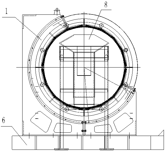
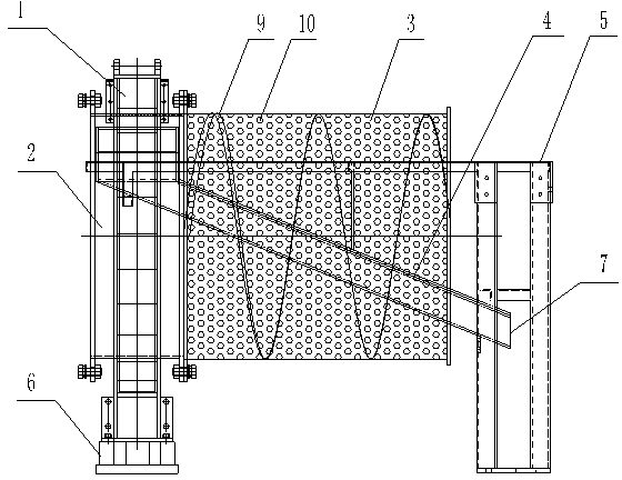
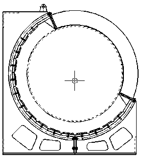
[0028] The present invention will be further described below in conjunction with accompanying drawing, see Figure 1-10 :

[0029] Quality separation screen (FZJ-I type), which includes magnetic system 1, drum 2, cylindrical screen 3, chute 4, chute frame 5, spiral structure 9 and machine base 6, drum 2 is made of non-magnetic stainless steel material In order to prevent the wear of the drum 2, wear-resistant materials (such as rubber materials) are provided (lined and pasted) on the inner wall of the drum 2, and the wear-resistant materials can be replaced separately after wear; the drum 2 and the cylindrical screen 3 are cylindrical cylinders with openings at both ends, and one end of the drum 2 is fixed by a flange at the ore discharge port of the mill [the drum is fixed on the end cover of the discharge port of the mill (ball mill), and the drum Rotate together with the mill], the drum 2 runs together with the rotation of the mill, the other end of the drum 2 is connected...


PUM


Abstract

The invention relates to equipment for removing iron magnetic impurities in materials and sieving the materials. A substance separating sieve is characterized by comprising a magnetic system, a rotary drum, a cylindrical sieve, a chute, a chute frame and an engine base, wherein the rotary drum is made of a non-magnetism-conducting stainless steel material; the rotary drum and the cylindrical sieve are cylindrical drum bodies with openings at two ends; one end of the rotary drum is fixed at an ore discharging opening of a mill by a flange and the other end of the rotary drum is in butt joint with one end of the cylindrical sieve through a flange; the magnetic system is arranged at the outer side of the rotary drum and the magnetic system is fixed on the engine base; the upper end of the chute penetrates through the cylindrical sieve and is located in the rotary drum; the lower end of the chute is located outside the cylindrical sieve and the chute is supported and fixed by the chute frame; the upper end of the chute is provided with a chute inlet and the lower end of the chute is provided with a chute outlet; and a washing water pipe is arranged at the chute inlet of the chute, and a water outlet end of the washing water pipe appoints to the upper part of the inner side of the rotary drum provided with the magnetic system. According to the substance separating sieve disclosed by the invention, crushed steel ball iron magnetic substances in ore discharged by the mill can be removed; and ore slurry of the ore discharged by the mill can be pre-graded and rough-grin materials are separated in advance.

Description

technical field [0001] The invention belongs to the technical field of machinery, and in particular relates to equipment for removing ferromagnetic impurities in materials and screening materials. technical background [0002] In the process of crushing materials in mining, building materials, chemical and other industries, because the steel balls added to the mill are eroded or broken during the grinding process, broken balls often occur. A lot of crushed balls flow out together with the slurry, and are broken and worn in the system in a cycle. Only when they are ground into powder can they be discharged with the fine particle materials. Cause serious wear and tear, greatly shorten their service life, reduce the working efficiency of the mill, and increase energy consumption. In order to solve the above problems, the method commonly used at present is to install permanent magnet or electromagnetic rollers and suspension iron removers on the belt conveyor. Due to the thick...

Claims


Application Information

Patent Timeline
IPC IPC(8): B03C1/30B03C1/12B07B1/22
Inventor 彭会清
Owner WUHAN UNIV OF TECH
Learn More