Wet-type vibrating-wire bipolar electrostatic coagulation deduster

A dust collector, electrostatic technology, applied in the field of wet vibrating wire dust collector, can solve the problems of weakening the condensation effect, difficult to capture dust droplets, etc., and achieve the effect of reducing the possibility of fouling, simple structure and convenient use

Inactive Publication Date: 2013-04-24
WUHAN UNIV OF SCI & TECH +3
View PDF8 Cites 12 Cited by
  • Summary
  • Abstract
  • Description
  • Claims
  • Application Information

AI Technical Summary

Problems solved by technology

Although the particle purification efficiency of the charged water mist vibrating wire washing dust collector has been improved, there are still the following shortcomings: First, the pre-charging method is adopted, and there is only Coulomb electrostatic attraction between the charged droplets and dust and the vibrating wire, but no electric field S

Method used


Image

  • Wet-type vibrating-wire bipolar electrostatic coagulation deduster
  • Wet-type vibrating-wire bipolar electrostatic coagulation deduster
  • Wet-type vibrating-wire bipolar electrostatic coagulation deduster

Examples


Example Embodiment

[0024] Example 1

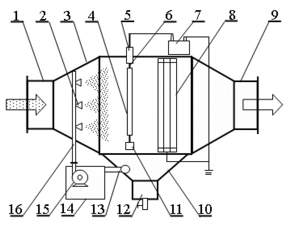
[0025] like figure 1 and figure 2 The wet-type vibrating wire bipolar electrostatic condensing and precipitator shown has a shell 3 with two ends in the shape of a prism. The bottom of the body 3 is provided with a mud bucket 10, and the bottom of the mud bucket 10 is provided with a slurry outlet 12. The mud bucket 10 is connected to the sedimentation tank 14 through the overflow pipe 13, and the water pump 15 is arranged in the sedimentation tank 14, and the water pump 15 is connected to the atomizing nozzle 2 through the circulating liquid pipe network 16, and the atomizing nozzle 2 is arranged in the housing 3 and is located in the inlet On the intake channel of the trachea 1. A single-layer vibrating wire grid 4 and a multi-layer vibrating wire grid 8 are sequentially arranged in the housing 3 between the atomizing nozzle 2 and the air outlet pipe 9 . The single-layer vibrating wire grid 4 is connected to the high-voltage pole of the DC high-volta...

Example Embodiment

[0030] Example 2

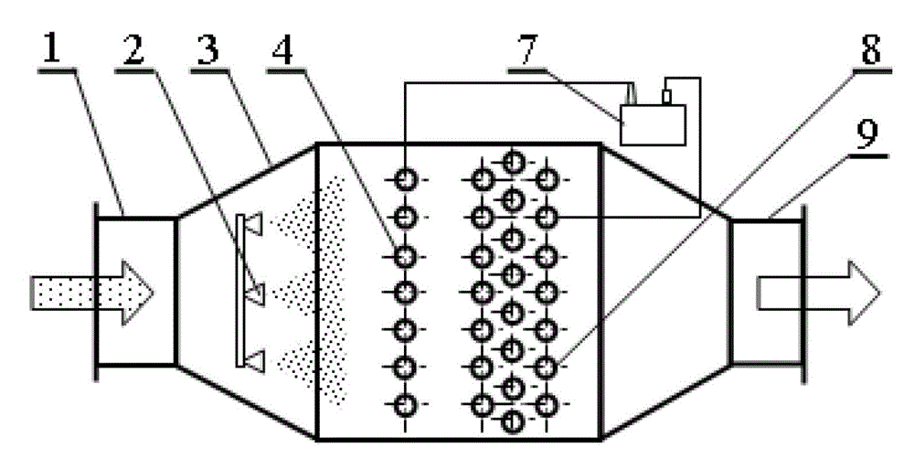
[0031] The main structure and working principle of embodiment 2 and embodiment 1 are basically the same, the only difference is that there are two sets of single-layer vibrating wire grids 4 and multi-layer vibrating wire grids 8 that cooperate with each other, two groups of single-layer vibrating wire grids 4 and The multi-layer vibrating wire grids 8 are arranged in series in sequence, and its structure is as follows Figure 4 shown. Embodiment 2 is suitable for the situation where the concentration of polluting gas is very high, and the dust cannot be fully removed and purified only through a set of single-layer vibrating wire grids 4 and multi-layer vibrating wire grids 8 . In this way, after the polluted gas is processed through the first set of single-layer vibrating wire grids 4 and multi-layer vibrating wire grids 8, the untrapped ultrafine particles pass through the second set of single-layer vibrating wire grids 4 and multi-layer vibrating wire gr...


PUM

PropertyMeasurementUnit
Diameteraaaaaaaaaa

Abstract

The invention relates to a wet-type vibrating-wire bipolar electrostatic coagulation deduster. The deduster comprises a shell, wherein one end of the shell is communicated with an air inlet pipe, the other end of the shell is communicated with an air outlet pipe, bottom of the shell is provided with a slurry bucket; bottom of the slurry bucket is provided with a slurry discharging port, the slurry bucket is connected with a sedimentation tank through an overflow pipe; the sedimentation tank is provided with a water pump which is connected with an atomizing nozzle through a circulating fluid pipe network; and the atomizing nozzle is arranged in the shell and on an air inlet channel of the air inlet pipe. The shell is further provided with a monolayer vibrating-wire grid and a multilayer vibrating-wire grid cooperating with each other and located between the atomizing nozzle and the air outlet pipe, wherein the monolayer vibrating-wire grid and the multilayer vibrating-wire grid are respectively connected with two electrodes of a DC high voltage power supply. The deduster has advantages of simple structure, low resistance, low energy consumption and large treatment amount for flue gas per unit area.

Description

technical field [0001] The invention relates to a wet vibrating wire dust collector, in particular to a wet vibrating wire bipolar electrostatic coagulation dust collector capable of efficiently trapping fine dust particles and water mist. Background technique [0002] The development of wet vibrating wire dust collector began in the late 1980s. For example, the Chinese invention patent No. 88100315.8 discloses a wet fiber grid dust collector. The dust collector has the advantages of small space occupied by unit processing air volume and low energy consumption. It is suitable for a wide range of dust concentrations, but its corrosion resistance is poor, and its service life is greatly reduced when it encounters corrosive fumes. In the 1990s, wet vibrating wire dust collectors using corrosion-resistant metal fibers appeared. For example, the Chinese invention patent No. 98229977.X disclosed a dust removal system for wet vibrating wire grids. Although the dust collector has th...

Claims


Application Information

Patent Timeline
IPC IPC(8): B03C3/16B03C3/01B03C3/40
Inventor 向晓东吴高明肖扬袁文博王聪余新明石零
Owner WUHAN UNIV OF SCI & TECH
Why Eureka
Try Eureka