Oil-water cooler used for sliding bearing

A technology of oil-water cooler and sliding bearing, which is applied in the direction of bearing cooling, bearing components, shafts and bearings, etc. It can solve the problems of burning tiles, accelerating the corrosion of cooler pipes, and cracking of cooler pipes, so as to speed up the corrosion speed, elimination of cooler corrosion, and shortened service life

Active Publication Date: 2013-04-24
HUNAN CHONGDE IND TECH
View PDF5 Cites 4 Cited by
  • Summary
  • Abstract
  • Description
  • Claims
  • Application Information

AI Technical Summary

Problems solved by technology

[0002] The oil-water cooler is the key part of the oil-immersed self-lubricating vertical sliding bearing. It takes away the heat generated during the operation of the bearing through the circulating cooling water to maintain the continuous operation of the bearing. Therefore, the replacement of the cooler by the vertical bearing unit There are high requirements for thermal efficiency, service life and reliability; however, at present, oil-water coolers usually have an upper water inlet and outlet structure, that is, a high-level water inlet and outlet structure. This inlet and outlet water structure has serious defects in use: due to , water outlet, the cooling water remaining inside the cooler pipe cannot be discharged in time when the unit is shut down for a long time, which not only accelerates the corrosion of the cooler pipe, but also causes the cooler pipe to swell and crack when the cooling water freezes at low temperature, and the oil-water mixture causes the bearing bush The temperature is too high during operation, and even the phenomenon of tile burning occurs. Once the tiles are burned, the unit will not operate normally and cause major economic losses.

Method used


Image

  • Oil-water cooler used for sliding bearing
  • Oil-water cooler used for sliding bearing
  • Oil-water cooler used for sliding bearing

Examples


Embodiment Construction

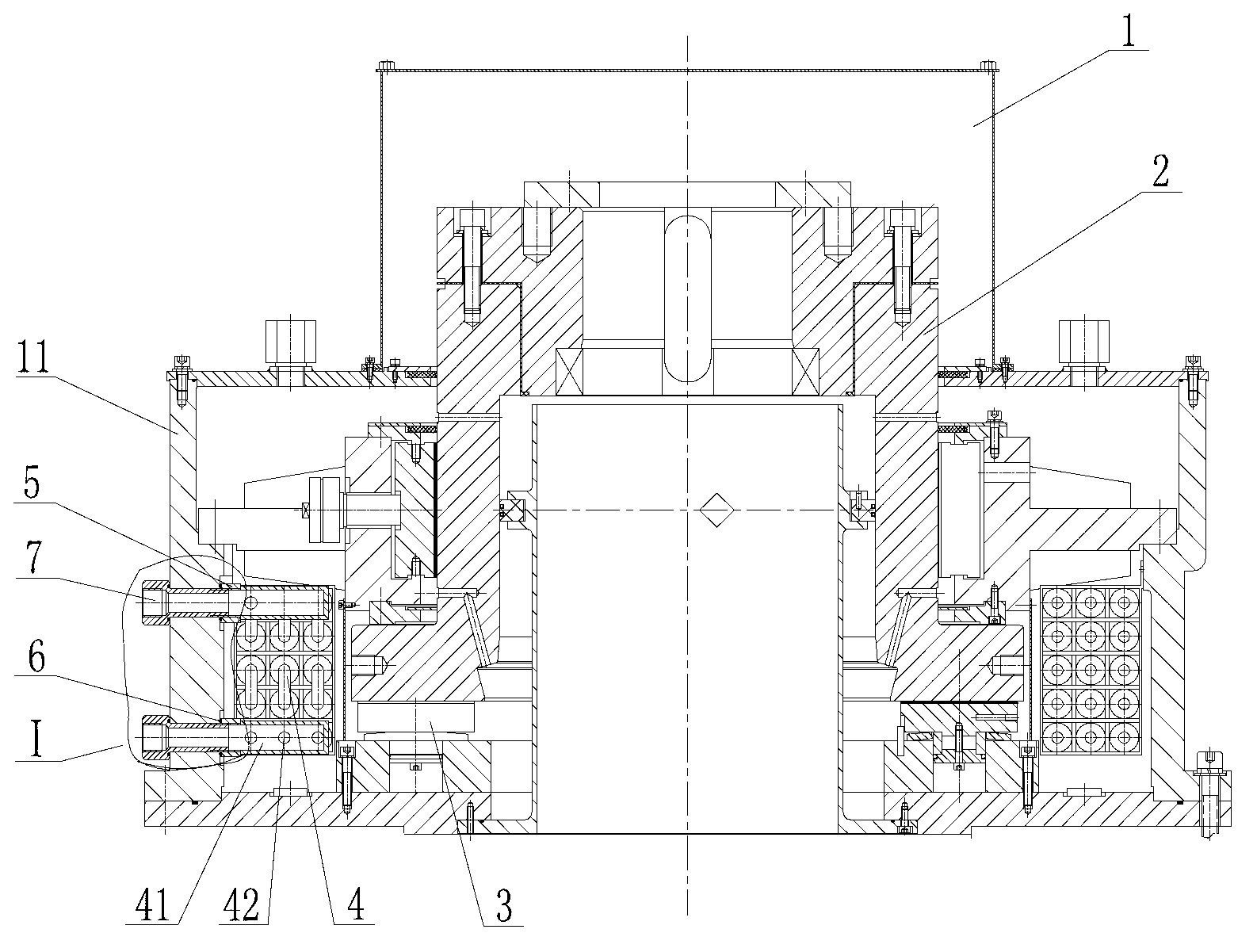
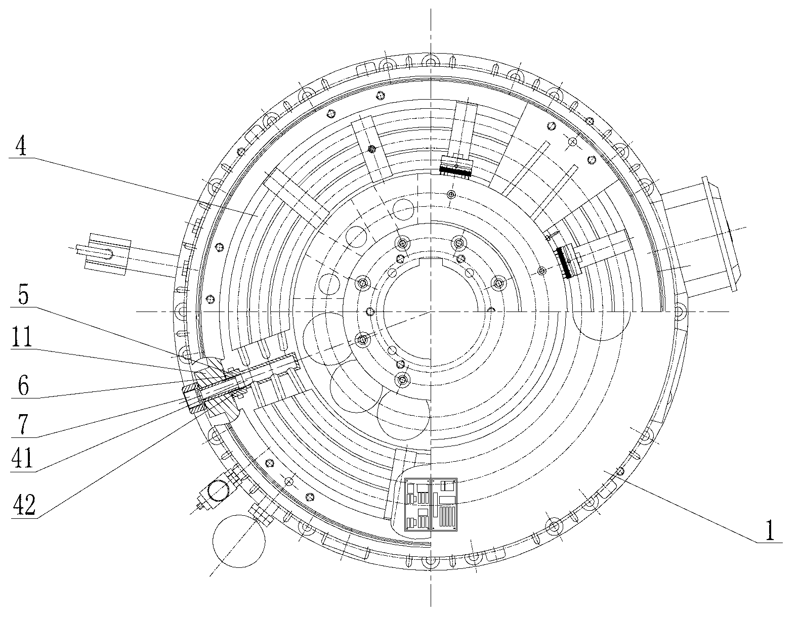
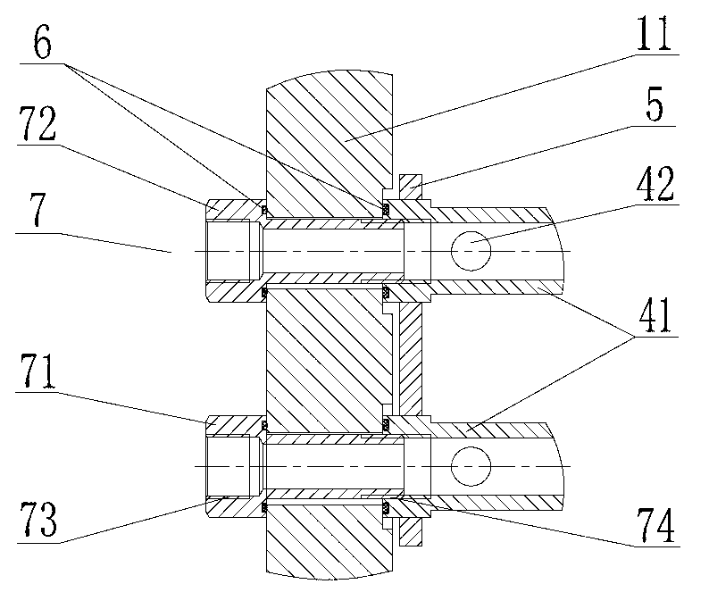
[0027] As shown in the accompanying drawings, an oil-water cooler for sliding bearings uses a bearing oil tank 1 as an intermediate connecting body, where the radial pad 2 in the center of the bearing oil tank 1 is combined with the rotating component thrust head 3 connected to the rotor of the main engine There are more than five layers of cooler pipes 4 spirally arranged on the outer periphery of the cooler pipe 4. The connecting joints 41 of the cooler pipes 4 are horizontal and pass through the wall of the box body 11 and the connecting plate 5 and the sealing ring 6 in the lower inner cavity of the box body 11. Transition water pipes Connect the joint 7 to realize the communication between the cooler pipe 4 and the external water supply system of the bearing oil tank 1; in order to prevent system leakage, the sealing ring 6 is arranged on the transition water pipe joint 7 on both sides of the box body 11; in order to ensure the reliability of the connection and the channel ...


PUM


Abstract

The invention discloses an oil-water cooler used for a sliding bearing. According to the oil-water cooler, a bearing oil tank is adopted as a middle connector; a plurality layers of cooler tubes are arranged in a spiral manner at the periphery of the joint part of a radial tile in the center inside the bearing oil tank and a rotational member thrust head connected with a host machine rotor; the connection joint of the cooler tubes is horizontally arranged and is connected with a transit water tube joint which penetrates through a box body wall, a connecting plate and a sealing ring, so that the technical scheme that the cooler tubes are communicated with a water supply system outside the bearing oil tank is realized. Defects that in the conventional upper intake and outtake water oil-water cooler used for a bearing, the corrosion of a cooler pipeline is accelerated as the cooling water remained inside the cooler cannot be discharged in time when a machine set is shut down for a long time, and that the cooler pipeline cracks as the cooling water is frozen in low temperature, are avoided, and the problems that the lubrication cooling effect is poor, the tile of the bearing is combusted and the like caused by the defects of a high position intake and outtake water oil-water cooler are solved, and therefore, the oil-water cooler is applicable to products in match with various power equipment, and in particular applicable to products in match with various heavy-load machines.

Description

technical field [0001] The invention relates to an oil-water cooler for sliding bearings. Background technique [0002] The oil-water cooler is the key part of the oil-immersed self-lubricating vertical sliding bearing. It takes away the heat generated during the operation of the bearing through the circulating cooling water to maintain the continuous operation of the bearing. Therefore, the replacement of the cooler by the vertical bearing unit There are high requirements for thermal efficiency, service life and reliability; however, at present, oil-water coolers usually have an upper water inlet and outlet structure, that is, a high-level water inlet and outlet structure. This inlet and outlet water structure has serious defects in use: due to , water outlet, the cooling water remaining inside the cooler pipe cannot be discharged in time when the unit is shut down for a long time, which not only accelerates the corrosion of the cooler pipe, but also causes the cooler pipe ...

Claims


Application Information

Patent Timeline
Patent Type & Authority Applications(China)
IPC IPC(8): F16C37/00
Inventor 张亚宾刘小军罗碧周少华
Owner HUNAN CHONGDE IND TECH
Why Eureka
Try Eureka