Eureka AIR delivers breakthrough ideas for toughest innovation challenges, trusted by R&D personnel around the world.

Single Event Pulse Width Measurement Circuit

A single-particle pulse and width measurement technology, applied in pulse characteristic measurement and other directions, can solve the problems of small measurement pulse width, low measurement accuracy, and difficulty in implementation, and achieve the effects of low test cost, avoidance of interference, and high measurement accuracy.

Active Publication Date: 2015-08-05
INST OF MICROELECTRONICS CHINESE ACAD OF SCI
View PDF5 Cites 0 Cited by
  • Summary
  • Abstract
  • Description
  • Claims
  • Application Information

AI Technical Summary

Problems solved by technology

If a traditional oscilloscope or logic analyzer is used to measure the pulse width of a single event, the requirements for the operating frequency of the device are very high, the test cost is high and the implementation is very difficult
If the on-chip circuit is used for testing, the existing pulse width measurement method often uses an external input high-frequency signal to sample the pulse signal. The capture accuracy of this measurement method is affected by the frequency and performance of the sampling signal, and it is difficult in actual testing. Provides sampling signals with extremely high frequency and excellent waveform characteristics, so the range of measurable pulse width is small, the measurement accuracy is low, and it is not suitable for measuring the width of single event pulses

Method used


Image

  • Single Event Pulse Width Measurement Circuit
  • Single Event Pulse Width Measurement Circuit
  • Single Event Pulse Width Measurement Circuit

Examples


Embodiment Construction

[0030] In order to make the object, technical solution and advantages of the present invention clearer, the present invention will be described in further detail below in conjunction with specific embodiments and with reference to the accompanying drawings. While illustrations of parameters including particular values ​​may be provided herein, it should be understood that parameters need not be exactly equal to the corresponding values, but rather may approximate the values ​​within acceptable error margins or design constraints.

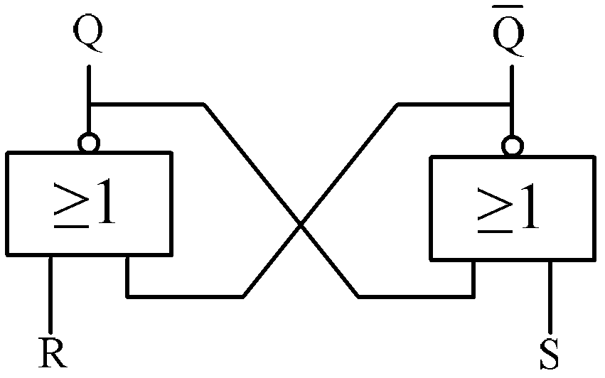
[0031] Such as figure 1 As shown, the pulse width measurement circuit provided in the embodiment of the present invention includes at least a two-stage circuit structure composed of a plurality of pulse attenuation circuits 101 and a plurality of bistable circuits 100, and the bistable circuit 100 includes at least one signal input terminal and a signal output terminal;

[0032] The first stage circuit structure of the pulse width measuring circuit...


PUM


Abstract

The invention discloses a measuring circuit of single-particle pulse width. The measuring circuit comprises a single-particle pulse signal generating circuit and at least one stage of a measuring circuit. The single-particle pulse signal generating circuit generates a single-particle pulse signal to be measured. A bistable circuit directly driven by the single-particle pulse signal to be measured forms a first stage of the measuring circuit. From a second stage of the measuring circuit on, each stage of circuit is composed of a pulse attenuator circuit and a bistable circuit. The input ends of the pulse attenuator circuits are connected with the signal input ends of the bistable circuits of former stages, and output ends of the pulse attenuator circuits are connected with the signal input ends of the bistable circuits of identical stage circuit. The output ends of a stage of preset bistable circuit or multiple stages of preset bistable circuits form the output result of the measuring circuit together, and the output result corresponds to the single-particle pulse width. The measuring circuit of the single-particle pulse width can improve the measuring accuracy of the single-particle pulse width, and reduce equipment cost.

Description

technical field [0001] The invention relates to the technical field of electric pulse signal measurement in the electronics industry, in particular to a single particle pulse width measurement circuit. Background technique [0002] With the development of technologies in aerospace, military and other fields, more and more integrated circuits need to work in radiation environments. The effects of radiation on integrated circuits fall into two main categories: single event effects and total dose effects. [0003] Among them, the single event transient effect is the main factor affecting the chip performance. When the chip is placed in a radiation environment, the surrounding energy particles will be injected into the chip, and a certain number of electron and hole pairs will be generated on the trajectory of the energy particles due to the action of ionizing radiation; The upper circuit node sinks, changing the node level. If there is no feedback loop in the circuit on the ...

Claims


Application Information

Patent Timeline
Patent Type & Authority Patents(China)
IPC IPC(8): G01R29/02
Inventor 宿晓慧毕津顺
Owner INST OF MICROELECTRONICS CHINESE ACAD OF SCI
Why Eureka
Eureka Blog
Learn More