
Liquid nozzle and manufacturing method thereof

A technology of a liquid nozzle and a manufacturing method, applied in printing and other directions, can solve the problems of low quality of liquid spray, high manufacturing cost, low yield of liquid nozzles, etc., and achieve scientific and reasonable manufacturing process, improve yield, and avoid binders. the effect of using

Active Publication Date: 2013-05-01
ZHUHAI SAILNER 3D TECH CO LTD
View PDF14 Cites 14 Cited by
  • Summary
  • Abstract
  • Description
  • Claims
  • Application Information

AI Technical Summary

Problems solved by technology

[0008] The main technical problem to be solved by the present invention is to provide a method for manufacturing a liquid spray head, by improving the formation process of the liquid chamber and the liquid spray hole, to solve the problem of low yield, high manufacturing cost and liquid spray quality of the liquid spray head in the prior art. not high problem

Method used


Image

  • Liquid nozzle and manufacturing method thereof
  • Liquid nozzle and manufacturing method thereof
  • Liquid nozzle and manufacturing method thereof

Examples


Embodiment Construction

[0034] The implementation of the present invention will be described in detail below in conjunction with the drawings and specific examples to help readers better understand the essence and beneficial effects of the present invention, but it should not be construed as any limitation on the scope of the present invention.

[0035] Please refer to Figure 1-10 , the manufacturing process of this embodiment is as follows:

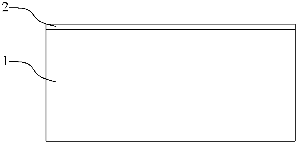
[0036] 1. Form a peeling layer 2 on the base 1

[0037] The material selection and the formation mode of the base 1 and the peeling layer 2 are conventional methods, such as figure 1 shown;

[0038] As the base 1, it is best to choose a material with good light transmission and heat resistance, so as to reduce the energy attenuation during the light irradiation process, and facilitate the subsequent peeling of the peeling layer. The transmittance of the base to irradiated light is preferably at least 10%, more preferably at least 50%. If the transmittance i...


PUM


Abstract

The invention provides a liquid nozzle and a manufacturing method thereof. The manufacturing method of the liquid nozzle comprises the following steps that an insulating material layer used as an oscillating plate is arranged on the common electrode surface of a piezoelectric element; a first thin layer made of optical imaging high molecular materials is arranged on the surface of the insulating material layer, and an area determined as a liquid cavity in the first thin layer is exposed for the first time; a second thin layer made of optical imaging high molecular materials is arranged on the surface of the exposed first thin layer, and an area determined as a liquid spraying hole in the second thin layer is exposed for the second time; and developing liquid is utilized to develop and remove unexposed materials from the first thin layer and the second thin layer, so as to form the liquid cavity and the liquid spraying hole. According to the liquid nozzle disclosed by the invention, integrated forming of the liquid cavity and the liquid nozzle is implemented through double exposure and one-time development, the strength of the liquid cavity and the rate of finished products are increased, and the liquid nozzle is favorable for improving the quality of printing equipment.

Description

technical field [0001] The invention relates to a liquid ejection head in a printing device and a manufacturing method of the liquid ejection head, in particular to a piezoelectric liquid ejection head used in an inkjet printing device and a manufacturing method thereof. Background technique [0002] With the popularization of printing equipment, the demand for improving the liquid jet head device of the existing printing equipment and improving the sharpness of the ink jet recording head is increasingly strong. In order to make the inkjet recording head high-definition, some corresponding improvement schemes have also been proposed. [0003] A common liquid ejection head structure generally includes a pressure chamber substrate, a nozzle plate glued on one side of the pressure chamber substrate, and a vibrating plate arranged on the other side of the pressure chamber substrate. The pressure chamber substrate is generally a silicon substrate (silicon wafer), and a plurality...

Claims


Application Information

Patent Timeline
IPC IPC(8): B41J2/14B41J2/16
Inventor 周毅李越
Owner ZHUHAI SAILNER 3D TECH CO LTD
Learn More