Optical information playback device, optical information playback method, and information recording medium

一种光学信息、再生装置的技术,应用在用光学方法记录/重现、数据记录、纳米光学等方向,能够解决光学极限尺寸限制、难信息再生、高密度化困难等问题,达到好再生信息的效果

Inactive Publication Date: 2013-05-01
PANASONIC CORP
View PDF5 Cites 6 Cited by
  • Summary
  • Abstract
  • Description
  • Claims
  • Application Information

AI Technical Summary

Problems solved by technology

[0005] However, in conventional optical storage systems, there is a problem that the size of the recording mark that can be reproduced (recording mark length) is limited by the NA (numerical aperture) of the objective lens and the diffraction limit determined by the wavelength of the reproduction light. The optical limit size is limited, and it is difficult to further increase the density
[0010] As a result, there is a problem that the change in the intensity of stray light detected corresponding to the presence or absence of recording marks is less than 0.00001% relative to the amount of reproduction light, for example, which is too small to perform good information reproduction.

Method used


Image

  • Optical information playback device, optical information playback method, and information recording medium
  • Optical information playback device, optical information playback method, and information recording medium
  • Optical information playback device, optical information playback method, and information recording medium

Examples


no. 1 Embodiment

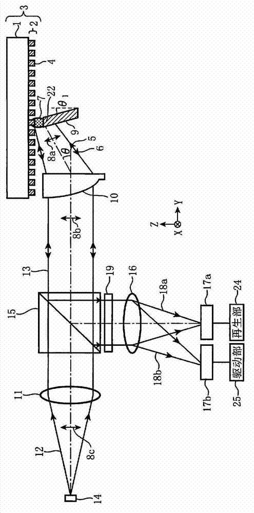
[0030] First, use figure 1 , figure 2 , image 3 (A) and image 3 (B) The optical information reproducing device, the optical information reproducing method, and the information recording medium according to the first embodiment of the present invention will be described in detail.

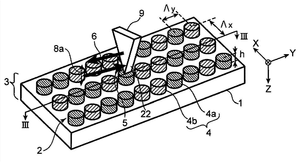
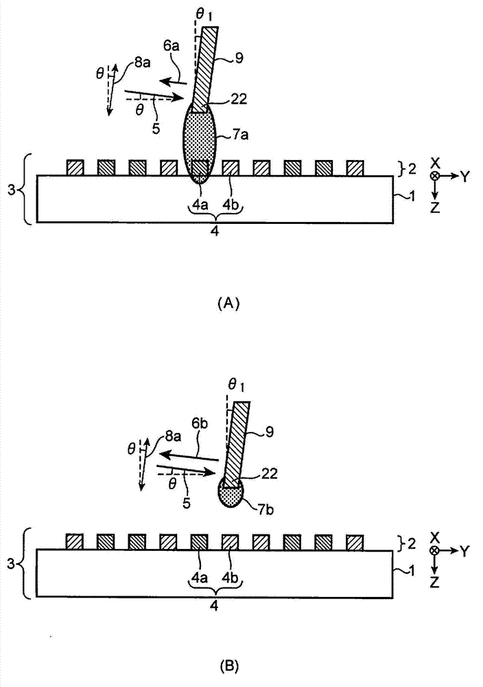
[0031] figure 1 is a schematic diagram of the structure of the optical information reproduction device according to the first embodiment of the present invention. figure 2 It is an explanatory diagram showing the plasmon resonance element of the optical information reproducing apparatus and the state of reproducing information from an information recording medium in the first embodiment of the present invention. image 3 (A) is an edge showing the situation near the plasmon resonance element when the recording region of the information recording medium is in the recording state in the first embodiment of the present invention and the degree of plasmon resonance is large. figure 2 Section...

no. 2 Embodiment

[0090] Next, an information recording medium according to a second embodiment of the present invention will be described. Figure 5 is a cross-sectional view showing the structure of an information recording medium according to a second embodiment of the present invention. The difference from the information recording medium 3 of the first embodiment is that a protective layer 23 having a positive sign of the real part of the dielectric constant is formed on the upper layer of the recording region 4 of the recording layer 2 formed on the substrate 1 . That is, the information recording medium 3 c further includes a protection layer 23 for protecting the recording area 4 , where the sign of the real part of the dielectric constant is positive, on the upper layer of the recording area 4 . By providing protective layer 23 , the environmental resistance of particles in recording region 4 formed of the recording material can be improved, and damage to recording region 4 due to cont...

no. 3 Embodiment

[0095] Next, for the optical information reproducing device of the third embodiment of the present invention, using Figure 6 , Figure 7 , Figure 8 (A) and Figure 8 (B) The description will focus on points different from the optical information reproducing apparatus of the above-mentioned first embodiment.

[0096] Figure 6 is a schematic diagram of the structure of an optical information reproduction device according to a third embodiment of the present invention. Figure 7 It is an explanatory diagram showing the plasmon resonance element of the optical information reproducing apparatus and the state of reproducing information from an information recording medium in the third embodiment of the present invention. Figure 8 (A) is an edge showing the situation near the plasmon resonance element when the recording region of the information recording medium is in the recording state and the degree of plasmon resonance is large in the third embodiment of the present inventi...


PUM

PropertyMeasurementUnit
wavelengthaaaaaaaaaa
diameteraaaaaaaaaa
reflectivityaaaaaaaaaa

Abstract

Provided are an optical information playback device, an optical information playback method, and an information recording medium, by which, if the size of a recording area is smaller than the diffraction limit of light, information can be favorably playbacked. An optical information playback device comprises a light source (14) which emits playback lights, and a resonance unit (22) arranged closely to a recording area (4) of a recording layer (2), wherein the resonance unit (22) is provided with a plasmon resonance element (9) which generates plasmon resonance between the recording area (4) and the resonance unit (22), a photodetector (17a) which detects reflection lights or transmitted lights from the plasmon resonance element (9) to which the playback lights are irradiated, and a playback unit (24) which assesses whether the recording area (4); is in a recorded state or in an unrecorded state on the basis of the detection signal from the photodetector (17a) and playbacks the information recorded in the recording area (4).

Description

technical field [0001] The present invention relates to an optical information reproducing device and an optical information reproducing method for optically reproducing information recorded on an information recording medium, and an information recording medium including at least a substrate and a recording layer. Background technique [0002] As an optical information reproducing device, an optical storage system using an optical disc such as a CD (Compact Disc), DVD, BD (Blu-ray Disc) or an optical card as an information recording medium has been put into practical use. [0003] The reproduction principle of the conventional optical storage system is simplified as Figure 10 shown. Figure 10 It is an explanatory diagram showing a part of the configuration of a conventional optical information recording and reproducing apparatus and a state of reproducing information from an information recording medium. [0004] In a conventional optical information recording and reprodu...

Claims


Application Information

Patent Timeline
Patent Type & Authority Applications(China)
IPC IPC(8): G11B7/005G11B7/1387G11B7/2531G11B7/2532G11B7/2533G11B7/2538
CPCB82Y20/00G11B7/2538B82Y10/00G11B7/2533G11B7/005B82Y30/00G11B7/1387G11B7/2531G11B7/2532
Inventor 盐野照弘小林良治
Owner PANASONIC CORP
Why Eureka
Try Eureka