
System and method for improving operation capacity of SCR (Silicon Controlled Rectifier) denitration device in electric power plant

A technology of operation capability and denitration, which is applied in chemical instruments and methods, separation methods, and dispersed particle separation, etc., can solve the problem that the denitration device 10 cannot be put into operation normally, the flue gas temperature at the outlet of the economizer 3 is lowered, and the water supply flow cannot be adjusted. It can improve the effective operation time, prolong the effective service life, and improve the denitrification ability.

Active Publication Date: 2013-05-08
ELECTRIC POWER RES INST OF GUANGDONG POWER GRID
View PDF5 Cites 24 Cited by
  • Summary
  • Abstract
  • Description
  • Claims
  • Application Information

AI Technical Summary

Problems solved by technology

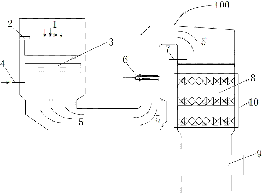
[0009] Since the boiler economizer 3 in the prior art cannot perform adjustable operation on its feedwater flow rate, and its feedwater flow rate changes little under any load under normal operation, therefore, as the operating load of the boiler decreases, the boiler outlet The flue gas volume is significantly reduced, and the temperature of the flue gas at the outlet of the economizer 3 will decrease accordingly, resulting in the temperature of the flue gas entering the denitrification device 10 after the heat exchange of the economizer 3 is lower than the minimum design operating temperature, so that the denitrification device 10 cannot work normally. put into operation

Method used


Image

  • System and method for improving operation capacity of SCR (Silicon Controlled Rectifier) denitration device in electric power plant
  • System and method for improving operation capacity of SCR (Silicon Controlled Rectifier) denitration device in electric power plant

Examples


Embodiment Construction

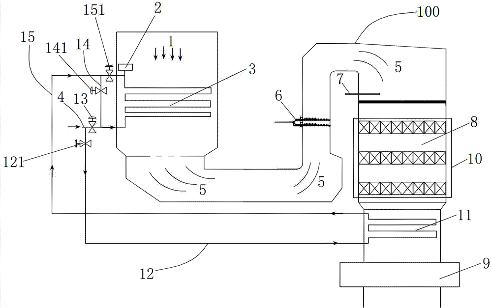
[0024] Such as figure 2 A system for improving the operation capacity of the SCR denitrification device in a power plant is shown, the system includes a steam drum 2, an economizer 3, a deflector 5, an ammonia Injection device 6, temperature sensor 7, denitrification device 10 and air preheater 9, the water inlet of economizer 3 is connected with economizer feed water inlet pipeline 4, and the water outlet of economizer 3 is connected with steam drum 2 The denitrification catalyst 8 is placed in the denitrification device 10, and the flue gas 1 passes through the denitrification device 10, the air preheater 9, and other follow-up equipment after heat exchange through various heat exchange equipment in the boiler flue. The system also includes a low-temperature heat exchanger 11, which is arranged in the flue between the denitrification device 10 and the air preheater 9, and the feedwater inlet pipeline 4 of the economizer is bypassed with the low-temperature heat exchanger 11...


PUM


Abstract

The invention discloses a system and a method for improving the operation capacity of an SCR (Silicon Controlled Rectifier) denitration device in an electric power plant. The system comprises an economizer, a guide plate, an ammonia injection device, a temperature sensor, a denitration device, a cryogenic heat exchanger and an air preheater, wherein an inlet pipeline of the cryogenic heat exchanger, which is connected to a water inlet of the cryogenic heat exchanger, is branched from a water supply inlet pipeline of the economizer, an outlet pipeline of the cryogenic heat exchanger is arranged between a water outlet of the cryogenic heat exchanger and a steam pocket, one series-connection pipeline is arranged between the water supply inlet of the economizer and the outlet pipeline of the cryogenic heat exchanger, a series-connection valve is arranged on the series-connection pipeline, an outlet valve of the cryogenic heat exchanger is arranged on the outlet pipeline of the cryogenic heat exchanger, an inlet flow control valve of the economizer is arranged on the water supply inlet pipeline of the economizer, so that parallel connection or series connection of the cryogenic heat exchanger and the economizer is realized. The invention also discloses the method for improving the operation capacity of SCR denitration device in the electric power plant.

Description

technical field [0001] The invention relates to the field of selective catalytic reduction denitrification method used in power plant boilers, and specifically refers to a system and method for improving the operation capacity of an SCR denitrification device in a power plant. Background technique [0002] Nitrogen oxides (NO, NO 2 and N 2 O) is one of the important sources of environmental pollution today, and these nitrogen oxides can cause a series of problems such as photochemical smog, acid rain, ozone layer depletion, and greenhouse effect. In order to meet the increasingly stringent emission requirements, power plants at home and abroad have begun to install and use denitrification devices one after another. Among many denitrification methods, selective catalytic reduction (SCR) denitrification devices have been widely used for their mature technology and stable denitrification efficiency. [0003] The SCR denitration reaction device mainly includes a reactor shell...

Claims


Application Information

Patent Timeline
IPC IPC(8): B01D53/90B01D53/56
Inventor 杨青山廖永进
Owner ELECTRIC POWER RES INST OF GUANGDONG POWER GRID
Learn More