Pipeline leakage automatic blocking valve

A pipeline leakage and automatic technology, applied in the direction of valve lift, valve details, valve devices, etc., can solve the problems of unsatisfactory plugging effect, complex system structure, long assembly time, etc., and achieve ideal plugging effect and high safety , the effect of short assembly time

Inactive Publication Date: 2013-05-08
张晖
View PDF7 Cites 3 Cited by
  • Summary
  • Abstract
  • Description
  • Claims
  • Application Information

AI Technical Summary

Problems solved by technology

[0003] The main problems of the above-mentioned sealing device and its sealing method are: it is necessary to stop the conveying medium befor

Method used


Image

  • Pipeline leakage automatic blocking valve

Examples


Embodiment Construction

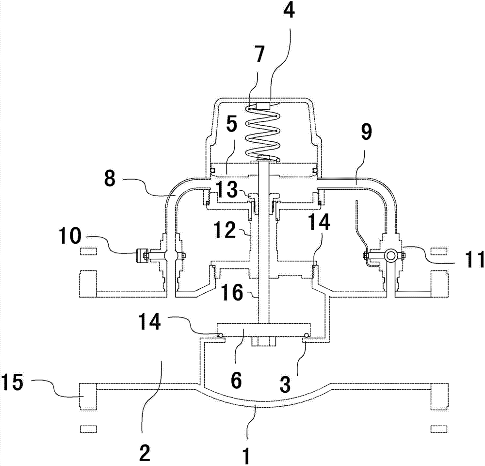
[0013] As shown in the figure, the pipeline leakage automatic sealing valve includes a valve body 1; the valve body 1 includes a main channel 2 and an automatic shut-off mechanism; the main channel 2 is fixed with a shut-off port 3; the automatic shut-off The mechanism includes a cylinder 4, a valve 6 and a piston 5 placed in the cylinder 4; the piston 5 is in motion with the inner wall of the cylinder 4, and its geometric center is fixedly connected to the valve 6 through a connecting rod 16; the top of the piston 5 is connected to the cylinder A thrust spring 7 is fixed between the tops of 4; the working surface of the valve 6 corresponds to the shut-off port 3 to ensure the opening and closing of the main channel 2; the first drainage is fixed on both sides of the cylinder 4 Branch 8 and second drainage branch 9; the two ports of the first drainage branch 8 and the second drainage branch 9 communicate with the inner cavity of the main channel 2 and the bottom area of ​​the i...


PUM


Abstract

The invention belongs to the field of risk source pipeline blocking devices, and particularly relates to a pipeline leakage automatic blocking valve. The pipeline leakage automatic blocking valve comprises a valve body (1), wherein the valve body (1) comprises a main channel (2) and an automatic cut-off mechanism, and a cut-off mouth (3) is fixedly arranged inside the main channel (2). The automatic cut-off mechanism comprises an air cylinder (4), a piston (5) and a valve (6), and the piston (5) is movably matched with the inner wall of the air cylinder (4), and is fixedly connected with the valve (6) through a connection rod (16). A thrust spring (7) is fixedly arranged between the top portion of the piston (5) and the top portion of the air cylinder (4). A first drainage branching (8) and a second drainage branching (9) are fixedly assembled on two sides of the air cylinder (4), and two end mouths of the first drainage branching (8) and the second drainage branching (9) are respectively communicated with the inner cavity of the main channel (2) and the bottom portion area of the inner cavity of the air cylinder (4). The pipeline leakage automatic blocking valve is simple in structure, few in assembling unit, short in assembling time, high in safety, small in dielectric loss, and ideal in blocking effect.

Description

technical field [0001] The invention belongs to the field of risk source pipeline sealing devices, and in particular relates to an automatic pipeline leakage sealing valve for quickly sealing the risk source pipeline in an emergency situation in which the risk source pipeline leaks. Background technique [0002] The existing pipeline leakage plugging mainly includes injection type plugging under pressure, external sealing type plugging, binding type plugging, cork plugging, metal plugging, injection type plugging and sticking type plugging. The pressurized plugging device mainly includes structural units such as clamps, injection valves, high-pressure injection guns, quick-fit joints, high-pressure oil delivery pipes, oil return tail joints, oil pressure reversing valve joints, and manual hydraulic oil pumps. It is mainly used in chemical accidents. The leakage of the flange in the middle, and the taper plug is mainly used for sealing when the pipeline breaks, while the exte...

Claims


Application Information

Patent Timeline
IPC IPC(8): F16K31/122F16K1/00
Inventor 张晖
Owner 张晖
Why Eureka
Try Eureka