
Method for improving homogeneity of critical dimension of photomask

A key dimension and mask technology, which is applied in the direction of photo-plate making process of the original, optics, and pattern surface for photomechanical processing, and can solve problems such as poor uniformity of key dimensions

Inactive Publication Date: 2013-05-08
SHANGHAI HUALI MICROELECTRONICS CORP
View PDF4 Cites 1 Cited by
  • Summary
  • Abstract
  • Description
  • Claims
  • Application Information

AI Technical Summary

Problems solved by technology

[0005] The technical problem to be solved by the present invention is to address the above-mentioned defects in the prior art, and provide a method that can solve the problem of poor uniformity of critical dimensions caused by the atomization effect of the mask during exposure, and finally improve the uniformity of critical dimensions of the mask as a whole. sexual method

Method used


Image

  • Method for improving homogeneity of critical dimension of photomask
  • Method for improving homogeneity of critical dimension of photomask
  • Method for improving homogeneity of critical dimension of photomask

Examples


Embodiment Construction

[0025] In order to make the content of the present invention clearer and easier to understand, the content of the present invention will be described in detail below in conjunction with specific embodiments and accompanying drawings.

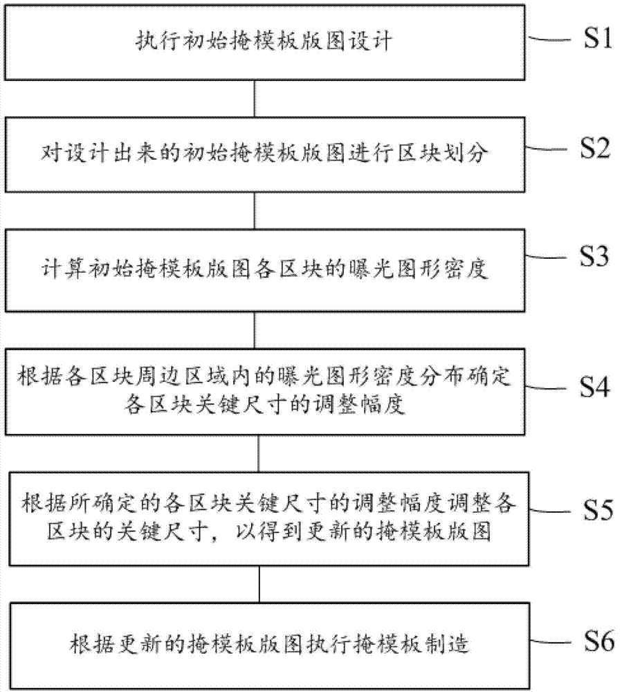
[0026] figure 1 A flow chart of a method for improving the critical dimension uniformity of a photomask template according to a preferred embodiment of the present invention is schematically shown.

[0027] More specifically, as figure 1 As shown, the method for improving the critical dimension uniformity of a photomask according to a preferred embodiment of the present invention includes:

[0028] The first step S1 is to perform an initial mask layout design; wherein, the initial mask layout design can be performed by any means known in the prior art.

[0029] The second step S2 is to divide the designed initial mask layout into blocks; preferably, the blocks can be divided according to a fixed size, for example, a cell with a size of 20umx20...


PUM


Abstract

The invention provides a method for improving homogeneity of critical dimension of a photomask. The method comprises the steps of: firstly, carrying out initial mask layout design; secondly, dividing the designed initial mask layout to blocks; thirdly, calculating the density of an exposure figure of each block of the initial mask layout; fourthly, determining the adjustment range of the critical dimension of each block according to the density distribution of the exposure figure in the peripheral area of each block; fifthly, adjusting the critical dimension of each block according to the determined adjustment range of the critical dimension of each block, thereby obtaining an updated mask layout; and sixthly, manufacturing a mask according to the updated mask layout.

Description

technical field [0001] The invention relates to the field of semiconductor manufacturing, and more specifically, the invention relates to a method for improving the uniformity of critical dimensions of a photomask. Background technique [0002] In the integrated circuit manufacturing process, the designed circuit is usually transferred to the mask plate by laser beam or electron beam, and then the pattern on the mask plate is transferred to the silicon wafer by exposure. [0003] However, since the electron beam is easy to reflect repeatedly on the surface of the photomask substrate and the exposure cavity (fogging effect), the photoresist in the area with a larger pattern area in the exposed area accepts more electrons than the photoresist in other areas. Therefore, under the same exposure energy, after development, the critical dimension of the photoresist in the region with a larger proportion of the pattern area in the exposure area of ​​the mask plate of the positive ph...

Claims


Application Information

Patent Timeline
IPC IPC(8): G03F1/72
Inventor 阚欢魏芳张旭升
Owner SHANGHAI HUALI MICROELECTRONICS CORP
Learn More