Magnet isolation drive circuit

A technology of isolation drive and gate drive circuit, applied in electrical components, high-efficiency power electronic conversion, output power conversion devices, etc., to reduce switching losses, reduce the peak value of resonant voltage, and prevent false turn-on

Inactive Publication Date: 2013-05-08
NANJING UNIV OF AERONAUTICS & ASTRONAUTICS
View PDF3 Cites 20 Cited by
  • Summary
  • Abstract
  • Description
  • Claims
  • Application Information

AI Technical Summary

Problems solved by technology

[0005] The technical problem to be solved by the present invention is to provide an improved solution for the problems of the power switch tube malfunction caused by the leakage inductance of the isolation transformer in the existing magnetic isolation drive circuit scheme, the limitation of the driving current capabili

Method used


Image

  • Magnet isolation drive circuit
  • Magnet isolation drive circuit
  • Magnet isolation drive circuit

Examples


Embodiment Construction

[0021] In order to clearly illustrate the technical solution in the present invention, the implementation of the technical solution will be further described in detail below in conjunction with the accompanying drawings:

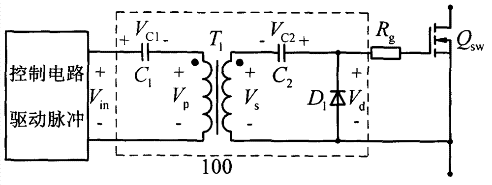
[0022] Figure 5 It shows a schematic structural diagram of a magnetic isolation drive circuit provided by the present invention, the magnetic isolation drive circuit includes: a control circuit for generating drive pulses, the control circuit is powered by the first DC power supply VCC1, and the Isolation drive transformer T 1 , the isolation drive transformer T 1 The input side and the output side of the same name are in phase; connected to the control circuit and the isolation drive transformer T 1 The first capacitor C between the same-named terminals on the input side 1 , with the isolation drive transformer T 1 The second capacitor C connected in series with the terminal of the same name on the output side 2 , connected to the second capacitor C ...


PUM


Abstract

The invention relates to a magnet isolation drive circuit which is applied to a power switch tube of a power supply switch, in particular to the magnet isolation drive circuit which is applied to a silicon carbide power metal oxide semiconductor (MOS) tube. The magnet isolation drive circuit comprises a control circuit, a first capacity C1, an isolation driver transformer T1, a second capacity C2, a light emitting diode D1, a drive pulse amplifying circuit which is connected to the light emitting diode D1 in parallel, a voltage-regulator tube ZD1, a capacity C3 which is connected to the voltage-regulator tube ZD1 in parallel, a resistance R1 and a drive resistance Rg. The magnet isolation drive circuit effectively avoids leakage inductance of a side edge of a transformer T1 on a switch tube, reduces a drive voltage peak value, reduces possibility of breaking down the switch tube, is high in current driving capacity and improves switching frequency of the switch tube. A drive pulse possesses a negative voltage, is capable of effectively preventing from being misled by the drive switch tube and improves work stability of a power supply. The magnet isolation drive circuit is suitable for various duty ratio signals, is simple in structure and low in cost and is particularly capable of fully expressing a performance advantage of the silicon carbide MOS tube.

Description

technical field [0001] The invention relates to a magnetic isolation drive circuit applied to a switching power switch tube of a switching power supply, in particular to a magnetic isolation drive circuit applied to a silicon carbide power MOS tube, and belongs to the technical field of drive circuits in the discipline of electrical technology. Background technique [0002] Magnetic isolation drive circuits are widely used in power supplies with high operating voltages to drive the power switch tubes in the power supply to turn on and off. With the continuous improvement of the power density and efficiency requirements of the switching power supply, high voltage and high frequency is one of the development trends of the widely used switching power supply. However, after decades of rapid development of power switching tubes based on silicon semiconductor materials, their performance is close to the theoretical limit of their materials, which has become a bottleneck that limit...

Claims


Application Information

Patent Timeline
IPC IPC(8): H02M1/08
CPCY02B70/1483Y02B70/10
Inventor 赵斌秦海鸿聂新马策宇袁源
Owner NANJING UNIV OF AERONAUTICS & ASTRONAUTICS
Why Eureka
Try Eureka