Rack for firing
A rack and setter technology, applied to furnaces, electric charge control, lighting and heating equipment, etc., can solve problems such as gas flow obstruction, poor product yield, hindering energy efficiency and mass production efficiency, etc., to achieve uniformity Excellent thermal performance, large heat radiation rate, and the effect of realizing energy efficiency and mass production efficiency
- Summary
- Abstract
- Description
- Claims
- Application Information
AI Technical Summary
Problems solved by technology
Method used
Image
Examples
no. 1 approach )
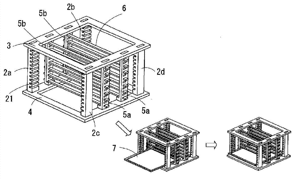
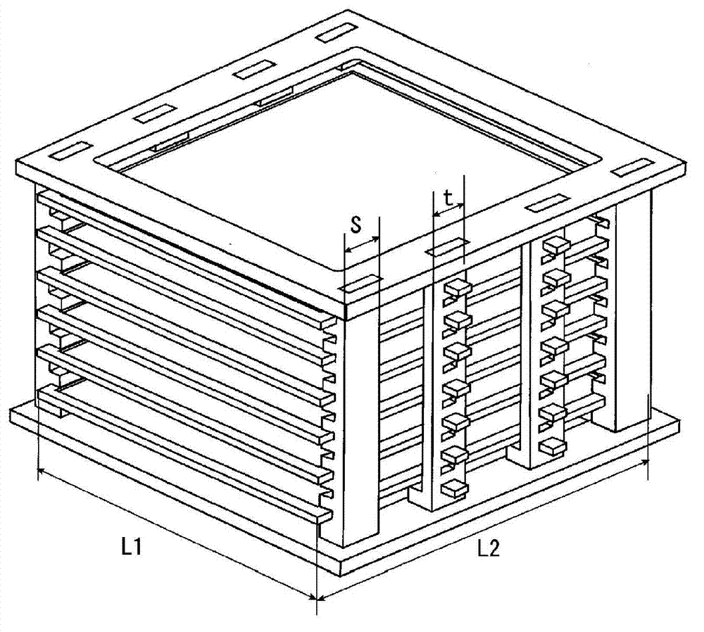
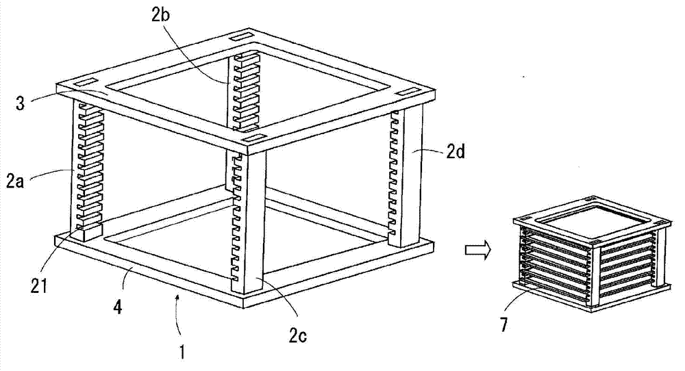
[0038] figure 1 and figure 2It is a figure which shows the 1st Embodiment of this invention. The firing frame 1 of the present embodiment has a roughly cubic shape, and the setter holding device includes: 4 vertical pillars 2 at the corners, which form the vertical sides of the 4 corners; a substantially mouth-shaped lower end support frame 4, which For supporting the lower end of these 4 corner vertical pillars 2 (2a, 2b, 2c, 2d); the upper end support frame 3 of roughly mouth shape, it is used for supporting the upper end of these 4 vertical pillars 2. Such as figure 1 As shown, this firing frame 1 is a device used by inserting a flat setter 7 .
[0039] Horizontal grooves 21 are formed on the inner surfaces of the vertical pillars 2 at each corner in parallel to the insertion direction of the flat setter 7, thereby constituting a setter holding mechanism. The flat setter 7 is inserted into the position of this horizontal groove part 21, and is held. A plurality of h...
no. 2 approach )
[0055] Figure 5 and Figure 6 It is a figure which shows the 2nd Embodiment of this invention. The firing frame 1 of the present embodiment is a device in which the setter holding device is constituted by a frame-shaped flat plate member 10 having a plurality of stacking protrusions 11 in the peripheral portion. exist Figure 5 In the preferred embodiment, the rectangular flat member 10 has quadrangular holes 12 on the left and right sides, and the flat setter 7 is placed on this part. At the left and right ends of one side of the plate member 10 and the central part of the side opposite to the side, respectively protrudingly provided with a stacking protrusion 11, protrudingly provided with a layer lower than the stacking protrusion 11 at a position around the hole 12. Protrusion 13 is used for positioning.
[0056] Figure 6 It is a side view of the state in which the flat setter 7 was hold|maintained by this setter holding apparatus and laminated|stacked in multiple l...
no. 3 approach )
[0058] Figure 7 and Figure 8It is a figure which shows the 3rd embodiment of this invention. The firing frame 1 setter holding device of this embodiment includes a pair of linear members 16 and a beam 18 arranged opposite to each other, wherein the pair of linear members 16 has a plurality of stacking protrusions 15; the beam 18 is erected on between the upper concave surfaces 17 of the respective stacking protrusions 15 . The stacking protrusion 15 is a mountain-shaped protrusion, and a recess 19 is formed on the lower side thereof. The beam 18 is a rod-shaped body with an angled cross section, and both ends thereof are fitted into the upper concave surface 17 of the stacking protrusion 15, and the flat setter 7 is placed thereon.
[0059] Figure 8 It is a side view of the state laminated|stacked multilayer after holding the flat setter 7 on these beams 18, and the flat setter 7 is shown by the dotted line. Such as Figure 8 As shown, the lower recess 19 fits into th...
PUM
| Property | Measurement | Unit |
|---|---|---|
| porosity | aaaaa | aaaaa |
Abstract
Description
Claims
Application Information
 - R&D
- Intellectual Property
- Life Sciences
- Materials
- Tech Scout
- Unparalleled Data Quality
- Higher Quality Content
- 60% Fewer Hallucinations
Browse by: Latest US Patents, China's latest patents, Technical Efficacy Thesaurus, Application Domain, Technology Topic, Popular Technical Reports.
© 2025 PatSnap. All rights reserved.Legal|Privacy policy|Modern Slavery Act Transparency Statement|Sitemap|About US| Contact US: help@patsnap.com


