
Modular integrated compressed air purification device

A technology for compressed air and purification devices, which is applied in combination devices, chemical instruments and methods, and dispersed particle separation. Reasonable and small temporary space utilization rate

Active Publication Date: 2013-05-15
ZHUHAI HECA PURIFICATION TECH
View PDF3 Cites 8 Cited by
  • Summary
  • Abstract
  • Description
  • Claims
  • Application Information

AI Technical Summary

Problems solved by technology

The dust, oil and water in the compressed air mix together to form an extremely harmful corrosive sludge, which will quickly wear out pneumatic equipment, block valves, and corrode pipelines, resulting in: air leakage, increased energy consumption, production stagnation, reduced Productivity, product obsolescence, increased manufacturing and maintenance costs, damage to tools and equipment, threats to health and safety, and impacted working conditions
Therefore, many manufacturers have conducted research and development on this problem and designed compressed air purification devices. At present, the main structure of the equipment components in the existing purification devices is a double-tower structure, and the cavities are connected by pipelines. Separators and high-efficiency filters are often used as separate mechanisms and are connected to the dryer through pipelines. The tower body adopts a welded structure, so there are the following defects: (1) The cavity material of the traditional air dryer is steel and welded (2) The air dryer needs 2 butterfly valves or cylinders driven by compressed air as the intake control valve, 2 butterfly valves driven by compressed air or 2 separate one-way valves as the outlet control valve, Two butterfly valves driven by compressed air are required as discharge control valves, which have a complex structure, a large number of valves, many fault points, and the butterfly valves are prone to leakage; It is high and takes up a lot of space, so it is not suitable for use in places with limited space; (4) The tower body of the traditional purification device is a sealed tank, which is not easy to maintain

Method used


Image

  • Modular integrated compressed air purification device
  • Modular integrated compressed air purification device
  • Modular integrated compressed air purification device

Examples


Embodiment Construction

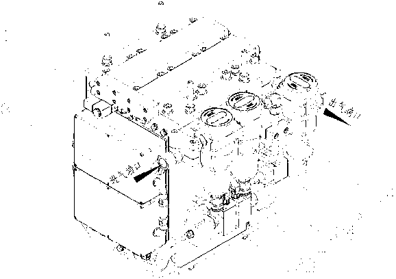
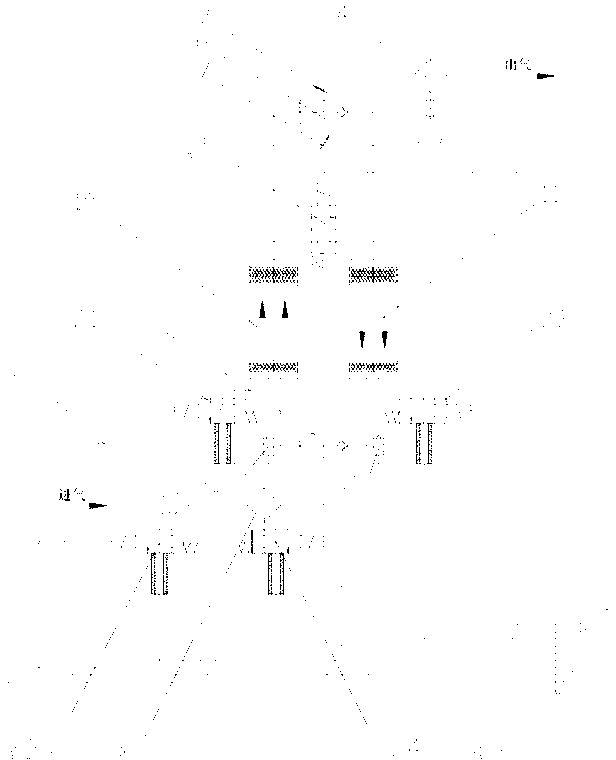
[0012] Such as figure 1 , figure 2 As shown, the modular integrated compressed air purification device of the present invention includes a dryer 1, an oil-water separator 2 arranged on the side wall of the dryer 1, a high-efficiency filter 3, a dust filter 4, and an electrical control device 8 And the discharge solenoid valve I21, the discharge solenoid valve II22, the discharge solenoid valve III23, the discharge solenoid valve IV24, and the rapid boost valve 25 electrically connected to the electrical control device 8, the unpurified compressed air output from the upstream air compressor passes through in sequence The oil-water separator 2, the high-efficiency filter 3, the dryer 1 and the dust filter 4 are processed and delivered to the downstream gas equipment. The dryer 1 includes a parallel double-chamber module structure, and The inlet valve assembly and the outlet valve assembly connected at both ends of the parallel double-cavity module structure, the inlet valve as...


PUM


Abstract

The invention discloses a modular integrated compressed air purification device, and aims to provide the modular integrated compressed air purification device characterized by a more compact structure, a small space occupation rate, more convenient installation and maintenance, and small energy consumption. The modular integrated compressed air purification device comprises a dryer (1), an oil-water separator (2) disposed on a side wall of the dryer (1), a high efficiency filter (3), and a dust filter (4). The unpurified compressed air output from an upstream air compressor is treated by the oil-water separator (2), the high efficiency filter (3), the dryer (1) and the dust filter (4) in order, and is then delivered to downstream gas consumption equipment. The modular integrated compressed air purification device provided in the invention can be widely applied in the field of compressed air purification.

Description

technical field [0001] The invention relates to a modular integrated compressed air purification device. Background technique [0002] Compressed air is an important power source widely used in various fields of industry. The air in all compressed air systems comes from the atmosphere. This air contains a lot of dust, water vapor, underburned hydrocarbons and bacteria. The lubrication system of the air compressor also produces pollutants such as wear particles and oil. The dust, oil and water in the compressed air mix together to form an extremely harmful corrosive sludge, which will quickly wear out pneumatic equipment, block valves, and corrode pipelines, resulting in: air leakage, increased energy consumption, production stagnation, reduced Productivity, product obsolescence, increased manufacturing and maintenance costs, damage to tools and equipment, threats to health and safety, and compromised working conditions. Therefore, many manufacturers have conducted research...

Claims


Application Information

Patent Timeline
IPC IPC(8): B01D50/00B01D53/26B01D53/02
Inventor 方能航李利陈顺景刘海峰
Owner ZHUHAI HECA PURIFICATION TECH
Learn More