Method and device of high-tension switch cabinet multi-fault diagnosis
What is AI technical title?
AI technical title is built by Patsnap AI team. It summarizes the technical point description of the patent document.
A technology of high-voltage switchgear and diagnosis method, which is applied in the directions of measuring devices, instruments, measuring electricity, etc., and can solve problems such as single detection function.
Inactive Publication Date: 2013-05-15
WENZHOU ELECTRIC POWER BUREAU +2
View PDF5 Cites 10 Cited by
Summary
Abstract
Description
Claims
Application Information
AI Technical Summary
This helps you quickly interpret patents by identifying the three key elements:
Problems solved by technology
Method used
Benefits of technology
Problems solved by technology
However, through the research of the existing technology, the applicant found that: the existing high-voltage switchgear test instrument has a single detection function, and can only monitor a certain type of fault, and cannot complete the simultaneous monitoring of various faults
For example: the use of infrared thermal imaging can only realize the monitoring of heating faults, while the high-frequency ultrasonic detection device can only detect partial discharge
Method used
Image
Click on the blue label to locate the original text in one second.
Reading with bidirectional positioning of images and text.
Examples
Embodiment 1
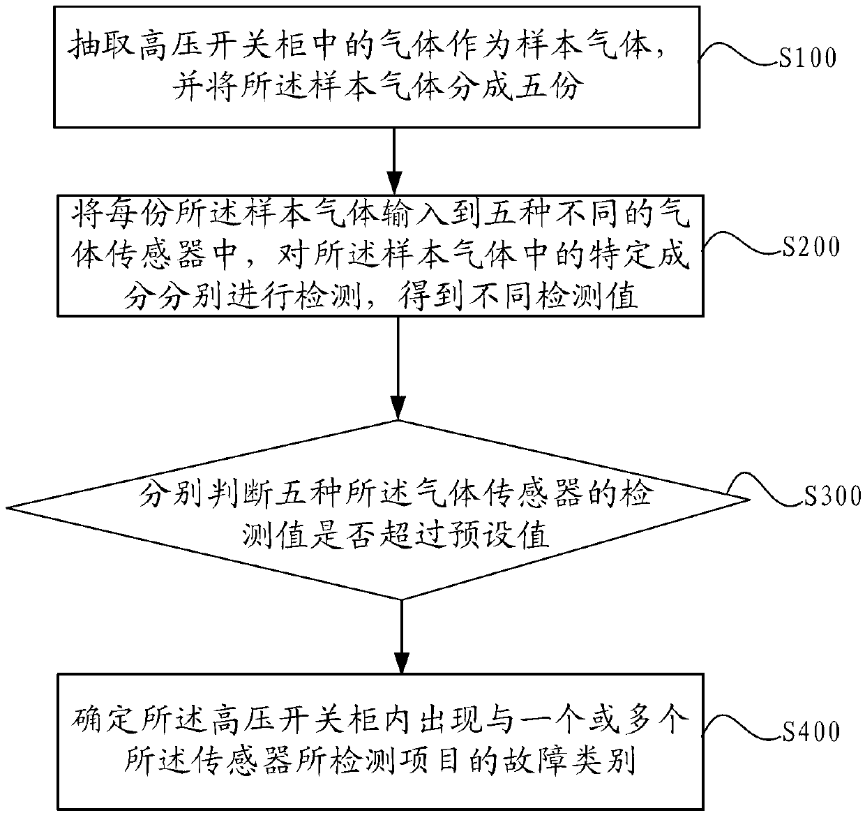
[0045] figure 1 It is a schematicflowchart of a method for diagnosing multiple faults of a high-voltage switchgear provided in the embodiment of the present application.
[0046] Such as figure 1 As shown, the method includes:
[0047] S100: Extracting gas in the high-voltage switchgear as a sample gas, and dividing the sample gas into five parts.
[0048]When there is a fault in the high-voltage switchgear, the fault here includes: contact overheating, partial discharge, SF6 leakage, etc., the gas composition in the high-voltage switchgear will change, for example: after partial discharge, it will cause ozone in the gas The amount increases; and when the contacts are overheated, the concentration of particulate matter in the air will increase. Therefore, analyzing the gas in the high-voltage switchgear can be used as a means of fault detection.
[0049] S200: Input each portion of the sample gas into five different gas sensors, respectively detect specific components in ...
Embodiment 2
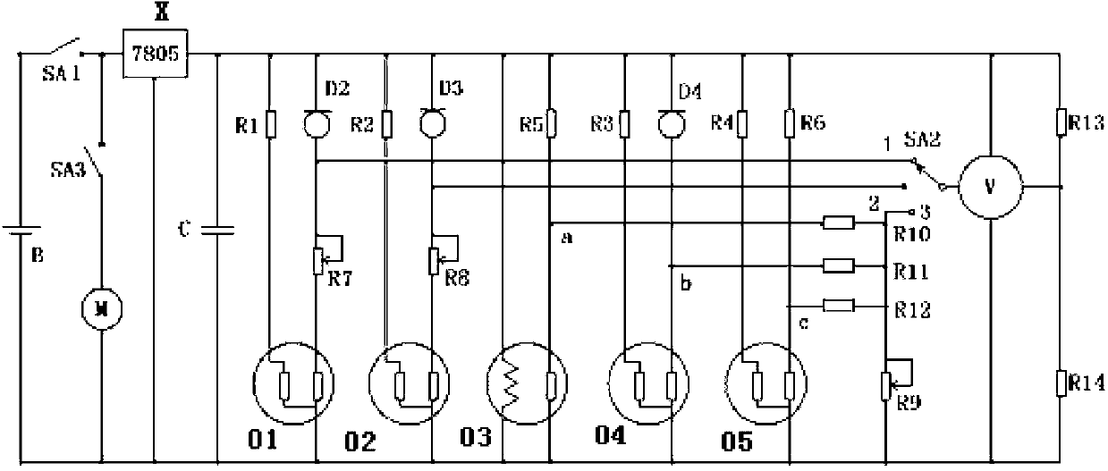
[0064] image 3 It is a schematic diagram of the circuit structure of a high-voltage switchgear multi-fault diagnosis device provided in the embodiment of the present application.
[0065] Such as image 3 As shown, the fault diagnosis device includes: suction switch SA3, vacuum pump M, ozone sensor 01, sulfurhexafluoride sensor 02, hydrogensulfide sensor 03, odor sensor 04, particle concentration sensor 05 (also called smoke sensor), multiple Gas channel (not shown in the figure), digital voltmeter V, first balancing resistor R13, second balancing resistor R14 and switch SA2.
[0066] B in the figure is the power supply, and the suction switch SA3 and the vacuum pump M are connected in series to the positive and negative ends of the power supply, and in order to facilitate the control of the entire circuit, a power supply SA1 is also provided at one end of the power supply B. In addition, in order to stabilize the voltage and current of the output of the power supply B, a...
PUM
Abstract
The invention discloses a method and a device of high-tension switch cabinet multi-fault diagnosis. The method of the high-tension switch cabinet multi-fault diagnosis comprises that gas in a high-tension switch cabinet is extracted as sample gas; the sample gas is divided into five parts; each part of the sample gas is delivered to five different kinds of gas sensors; ozone, sulfurhexafluoride, sulfuretted hydrogen, foreign taste and particle concentration in the sample gas are respectively detected to obtain different detection values; the detection values of the five kinds of gas sensors are respectively judged whether surpasses a preset value or not; and when the detection values of one or more gas sensors surpass the preset value, one or more fault categories corresponding to detection items detected by the gas sensors appear in the high-tension switch cabinet. Compared with the prior art, when detecting, the method of the high-tension switch cabinet multi-fault diagnosis can fast finish detecting multiple faults of the high-tension switch cabinet.
Description
technical field [0001] The present application relates to the technical field of high-voltage equipment detection, in particular to a method and device for multi-fault diagnosis of a high-voltageswitchgear. Background technique [0002] In the power system, the high-voltageswitchgear is responsible for the dual functions of closing and disconnecting the power lines and protecting the safety of the system. With the rapid development of the power system towards high voltage, large units, and large capacity, the power grid is expanding day by day and the unattended management of substations With the popularization and promotion of mode and comprehensive automation, the safe operation of high-voltage switchgear is becoming more and more important. When the switch blade contacts in the high-voltage switchgear and the joints of the power cable inlet and outlet lines are in poor contact, the contact resistance will increase, and heat will be generated when the load current flows....
Claims
Application Information
Patent Timeline
Application Date:The date an application was filed.
Publication Date:The date a patent or application was officially published.
First Publication Date:The earliest publication date of a patent with the same application number.
Issue Date:Publication date of the patent grant document.
PCT Entry Date:The Entry date of PCT National Phase.
Estimated Expiry Date:The statutory expiry date of a patent right according to the Patent Law, and it is the longest term of protection that the patent right can achieve without the termination of the patent right due to other reasons(Term extension factor has been taken into account ).
Invalid Date:Actual expiry date is based on effective date or publication date of legal transaction data of invalid patent.

