Large machinery equipment surface multifunction online processing and repairing device

A large-scale mechanical and multi-functional technology, applied in positioning devices, feeding devices, metal processing equipment, etc., can solve problems that affect production, long cycle time, and high cost, and achieve the effects of improving flexibility, reducing volume, and improving repair efficiency

Inactive Publication Date: 2013-05-22
SINOMA TECH & EQUIP GRP
View PDF7 Cites 6 Cited by
  • Summary
  • Abstract
  • Description
  • Claims
  • Application Information

AI Technical Summary

Problems solved by technology

The current method is to disassemble the deformed or worn equipment such as the tire of the rotary kiln as a whole, and transport it to the manufacturing plant for processing, which is costly and takes a long time to affect production.

Method used


Image

  • Large machinery equipment surface multifunction online processing and repairing device
  • Large machinery equipment surface multifunction online processing and repairing device
  • Large machinery equipment surface multifunction online processing and repairing device

Examples


Embodiment 1

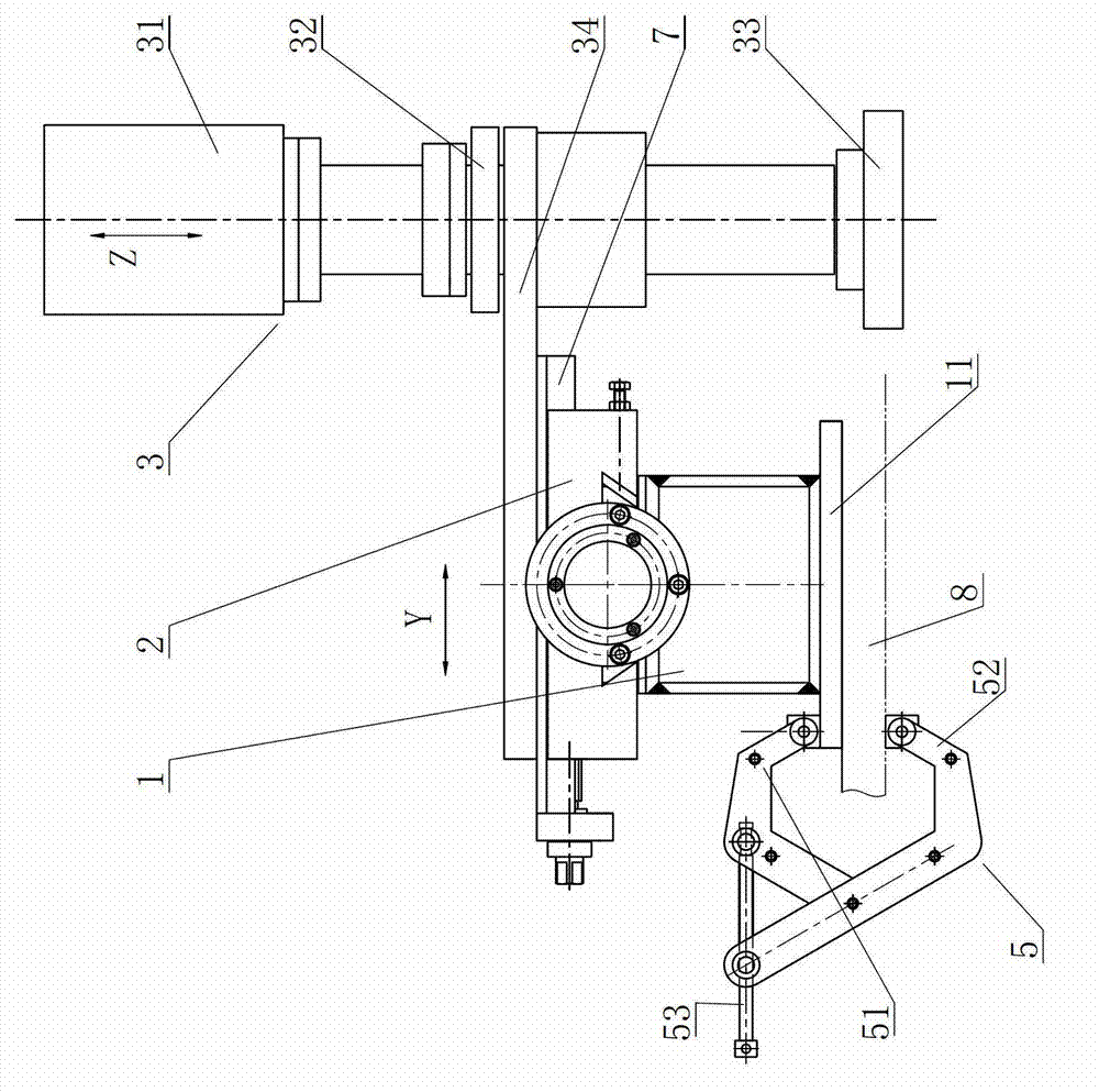
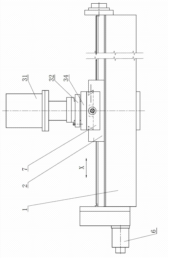
[0019] see figure 1 and figure 2 , a multifunctional online processing and repairing device for the surface of large-scale mechanical equipment, including a sliding table and a cross sliding table 2, the cross sliding table is connected with the sliding table in a sliding connection, in the form of a dovetail groove in this embodiment, the sliding table A feed drive device 6 is provided at one end of the sliding table, and a bottom plate 11 is provided at the bottom of the sliding table, which is connected with the fixed base 8 of large-scale mechanical equipment through a quick clamping device 5. Sliding plate, wherein the sliding plate 2 is slidingly connected with the sliding table, the sliding direction of the upper sliding plate 7 on the lowering plate is perpendicular to the sliding direction of the lowering plate on the sliding table, and the milling cutter assembly is installed on the upper sliding plate through the milling cutter assembly mounting plate 34 3. The m...

Embodiment 2

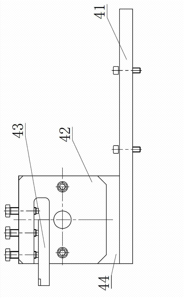
[0022] Such as image 3 , Figure 4 As shown, the difference between this embodiment and Embodiment 1 is that the tool assembly is not a milling cutter, but a turning tool is used. Specifically, the tool assembly is a turning tool assembly, which includes a turning tool installed at one end of the upper slide. Knife assembly mounting plate 41, the tool seat 42 installed on the turning tool assembly mounting plate, the tool seat 42 installed on the rotary seat 44 and the turning tool 43 fixed on the tool seat by screws in a manner of circumferential rotation connection .

[0023] When changing from using a milling cutter to a turning tool as a cutting tool, remove the milling cutter assembly mounting plate from the upper slide plate, replace the turning tool assembly mounting plate and the turning tool assembly, and use bolts to secure the turning tool assembly The installation plate and the upper slide plate are fixed, and the tool replacement work is completed. This device...


PUM


Abstract

The invention relates to a large machinery equipment surface multifunction online processing and repairing device. The large machinery equipment surface multifunction online processing and repairing device comprises a lower sliding table and a cross sliding table which is connected with the lower sliding table in a sliding mode. One end of the lower sliding table is provided with a feed driving device. A base board is arranged at the bottom of the lower sliding table. The base board is connected with fixed base pieces of the large machinery equipment through a fast clamping device. The cross sliding table comprises a lower sliding board and an upper sliding board. The lower sliding board and the upper sliding board are connected in a mutual sliding mode. The lower sliding board and the lower sliding table are connected in a sliding mode. The sliding direction of the upper sliding board is vertical to the sliding direction of the lower sliding board. The upper sliding board is provided with a milling cutter assembly through a milling cutter assembly mounting plate or is provided with a turning cutter assembly through a turning tool assembly mounting plate. The feed driving device or a cutting power device is a hydraulic motor or a servo motor. The large machinery equipment surface multifunction online processing and repairing device has the advantages that through the large machinery equipment surface multifunction online processing and repairing device fixed on the repaired large machinery equipment, a turning cutter or a milling cutter is utilized to repair broken surfaces, and critical components of the large machinery equipments are not needed to be removed, and therefore, online repair to the large machinery equipment is achieved and repair efficiency is improved.

Description

technical field [0001] This patent belongs to the technical field of online processing and repairing of equipment, and in particular relates to a multifunctional online processing and repairing device for the surface of large-scale mechanical equipment. Background technique [0002] Large-scale mechanical equipment such as rotary kilns and roller mills used in mining, metallurgy, building materials and other industries often experience irregular deformation or wear during operation, such as plane deformation of the base, wear of the outer circle of the rotating parts, etc., or It is because the stress in the manufacturing process is not completely released, and the aging effect is not fully in place. When the machine is transported to the site for installation, the stress release will cause the machine to deform. These irregular deformation or wear will lead to abnormal phenomena such as vibration and noise during the operation of the equipment, which will pose a threat to t...

Claims


Application Information

Patent Timeline
Patent Type & Authority Applications(China)
IPC IPC(8): B23P23/02B23Q5/34B23Q3/00
Inventor 王术菊黄继全侯龙华刘长雨衡琼枝母彩军靖运忠白文生
Owner SINOMA TECH & EQUIP GRP
Why Eureka
Try Eureka