Electric brush plating device of flat plate type metal component

A brush plating and parts technology, applied in jewelry and other directions, can solve the problems of high labor intensity of operators, unstable coating quality, short service life, etc., to improve the liquid phase mass transfer process, speed up electrodeposition, improve The effect of mechanical properties

Inactive Publication Date: 2013-05-22
ACADEMY OF ARMORED FORCES ENG PLA +1
View PDF5 Cites 16 Cited by
  • Summary
  • Abstract
  • Description
  • Claims
  • Application Information

AI Technical Summary

Problems solved by technology

In practical applications, in order to obtain a bright and fine coating, a certain amount of additives (wetting agent, brightener, leveling agent, etc.) It makes the maintenance of the plating solution difficult, and on the other hand, it will lead to more organic inclusions in the plating layer, which will affect the purity of the metal plating layer, and sometimes cause the increase of the brittleness of the plating layer and defects such as poor bonding between the plating layer and the metal substrate.
[0003] And although the existing electric brush plating device has advantages such as simple equipment, small volume, light weight, portability, being convenient to use on the spot or carry out field emergency repair at present, this electric brush plating device has the following defects: first, the plating pen The (anode) material is mostly made of high-purity fine graphite. This kind of plating pen has poor wear resistance and short service life; secondly, the brush plating device is mainly operated by hand, which has low efficiency, high labor intensity for operators, and poor coating quality. Defects such as unstable quality; third, there is a waste of plating solution, and more than 40% of the metal ions in the remaining plating solution cannot be effectively reused

Method used


Image

  • Electric brush plating device of flat plate type metal component
  • Electric brush plating device of flat plate type metal component

Examples


Embodiment Construction

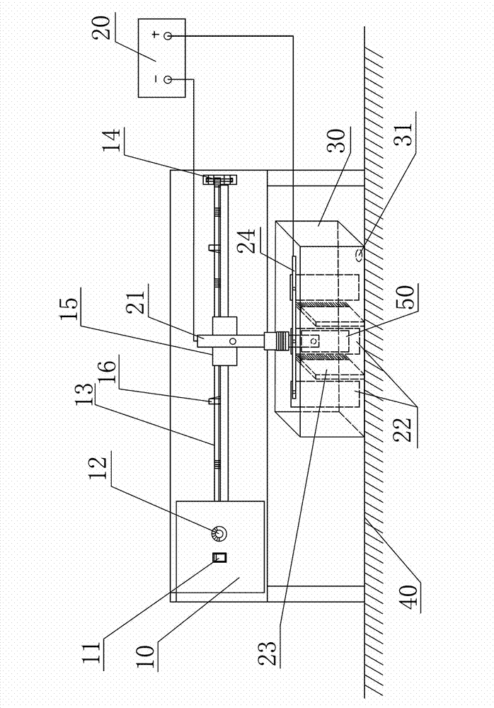
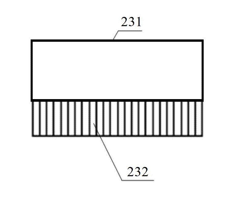
[0020] like figure 1 As shown, the brush plating device for flat metal parts of the present invention includes a motion control device, a brush 23, an anode plate 22 and a brush plating tank 30, wherein: the brush 23 and the anode plate 22 are fixedly mounted on the brush In the plating tank 30, the plating piece (ie, the flat metal part) 50 is installed on the motion control device via the insulating handle 21. In practice, the plating piece 50 can be fixed via the conductive block and the conductive rod (not shown in the figure). Installed on the insulating handle 21, the plating member 50 is located in the brush plating tank 30, the plated surface of the plating member 50 is arranged opposite to the anode plate 22 (referring to the plate surface of the anode plate 22), and the plating member 50 is opposite to the anode plate 22. The negative pole of the DC power supply 20 is connected. In practice, the plating member 50 is connected to the negative pole of the DC power supp...


PUM


Abstract

The invention discloses an electric brush plating device of a flat plate type metal component. The electric brush plating device comprises a movement control device, a brush, an anode plate and an electric brush plating groove, wherein the brush and the anode plate are fixedly mounted in the electric brush plating groove; a plating component is mounted on the movement control device and is positioned in the electric brush plating groove; the plated surface of the plating component is opposite to the anode plate; the plating component and the anode plate are respectively connected with the cathode and the anode of a direct-current power supply; the bristles of the brush face the plated surface of the plating component; the movement control device controls the plating component to do horizontal reciprocating rectilinear movement in the electric brush plating groove; when the plating component moves in front of the brush, the plated surface of the plating component do friction movement relative to the bristles of the brush. According to the electric brush plating device, the brush and the plating component do relative flexible friction movement in partial time during the whole electric brush plating process, so that the electric deposition speed is accelerated effectively; and a plating layer is prevented from generating pinholes, pocking marks, nodules and the like. Therefore, the quality of the plating layer is improved.

Description

technical field [0001] The invention relates to a metal surface brush plating device, in particular to a device for brush plating the surface of flat metal parts. Background technique [0002] At present, the current density allowed by traditional electrodeposition (electroplating) is very limited, generally less than 10A / dm 2 (Except for electroplating chromium), the electrodeposition speed is slow, the coating production cycle is long, and the roughness of the electrodeposited coating increases with the prolongation of the electrodeposition time, which is prone to problems such as coating inclusions and coarse grain size. In practical applications, in order to obtain a bright and detailed coating, a certain amount of additives (wetting agents, brighteners, leveling agents, etc.) are usually added to the plating solution, and the additives will be consumed with the progress of electrodeposition. It makes the maintenance of the plating solution difficult. On the other hand,...

Claims


Application Information

Patent Timeline
Patent Type & Authority Applications(China)
IPC IPC(8): C25D5/06C25D7/00
Inventor 胡振峰徐滨士吕镖汪笑鹤梁秀兵史佩京陈永雄蔡志海
Owner ACADEMY OF ARMORED FORCES ENG PLA
Why Eureka
Try Eureka