
Multi-mode multi-frequency global navigational satellite system receiver radio frequency front end device

A global navigation satellite, multi-mode and multi-frequency technology, applied in the field of satellite navigation, can solve the problems of weakening the possibility of receivers to process more signals, unfavorable system mode changes and adjustments, and complex circuit implementation, achieving low power consumption and compatibility. Strong performance and the effect of reducing system power consumption

Active Publication Date: 2013-05-22
WUHAN UNIV
View PDF5 Cites 52 Cited by
  • Summary
  • Abstract
  • Description
  • Claims
  • Application Information

AI Technical Summary

Problems solved by technology

Due to technical reasons such as large size and complex circuit implementation, most of the existing multi-mode receivers use a fixed dual-mode RF front-end design, that is, only use two of the four major systems for positioning. Reduces the receiver's ability to handle more signals, and fixed RF bands and bandwidths are not conducive to system mode changes and adjustments

Method used


Image

  • Multi-mode multi-frequency global navigational satellite system receiver radio frequency front end device
  • Multi-mode multi-frequency global navigational satellite system receiver radio frequency front end device
  • Multi-mode multi-frequency global navigational satellite system receiver radio frequency front end device

Examples


Embodiment Construction

[0027] The specific implementation of the present invention will be described in detail below in conjunction with the accompanying drawings.

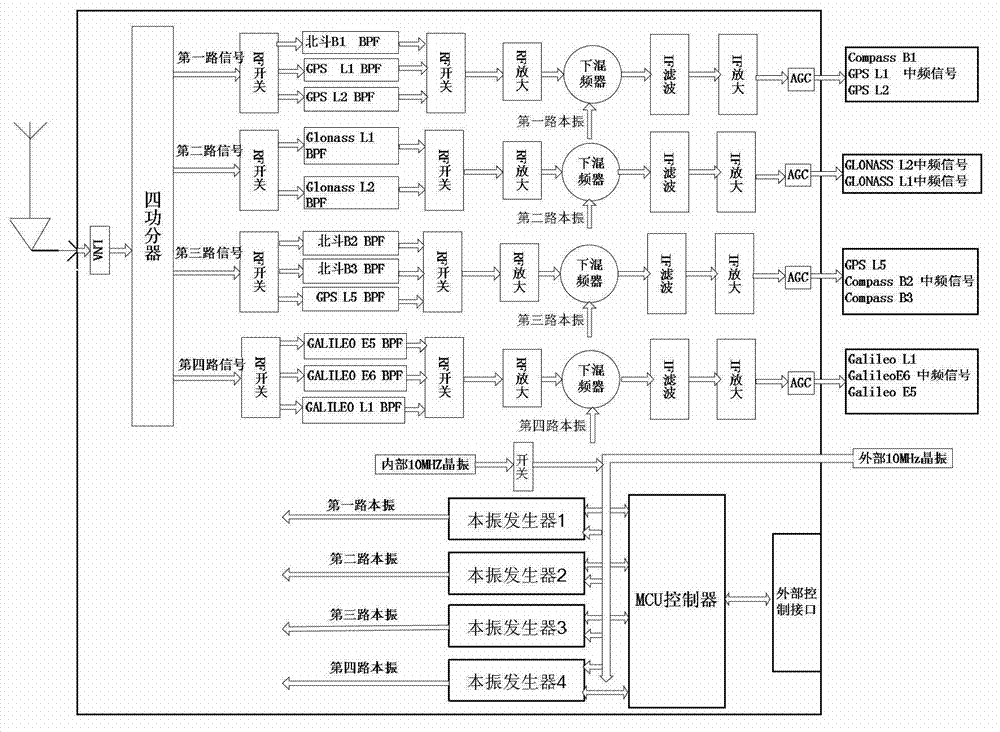
[0028] figure 1 For the structural block diagram of this specific implementation, there are four channels, including four radio frequency signal processing circuits. The satellite signal received by the GNSS receiver is sent to the four-way power splitter after passing through the low noise amplifier (Low Noise Amplifier, LNA), and the signal After the power is divided into four identical signals, they enter each radio frequency signal processing circuit respectively, and the circuit structure and principle of each radio frequency signal processing circuit are the same.

[0029] According to the bandwidth of the 11-band GNSS satellite signal, the present invention divides it into four channels of signals. The bandwidths of Beidou system B1 band signal, GPS L1 band signal and GPS L2 band signal are 2.046MHz, 2.046MHz, and 4.092MHz respe...


PUM


Abstract

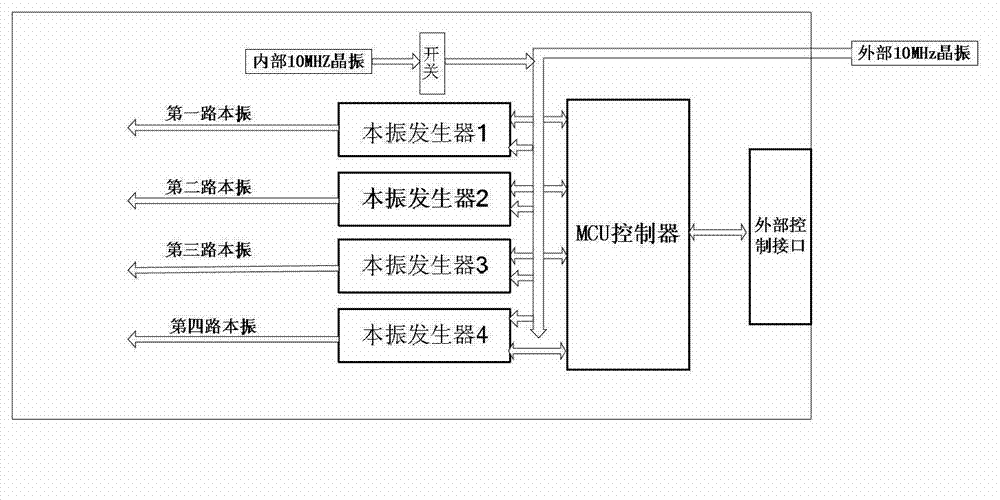
The invention discloses a multi-mode multi-frequency global navigational satellite system receiver radio frequency front end device. The device comprises a low-noise amplifier, a power divider, and multiple radio-frequency signal processing circuits, wherein the low-noise amplifier, the power divider, and the multiple radio-frequency signal processing circuits are connected in sequence. Each radio-frequency signal processing circuit comprises a first radio-frequency switch, a radio-frequency filter bank, a second radio-frequency switch, a radio-frequency amplifying module, a lower frequency mixing module, an intermediate frequency filter module, an intermediate frequency amplifying module, and an automatic gain control unit, wherein the first radio-frequency switch, the radio-frequency filter bank, the second radio-frequency switch, the radio-frequency amplifying module, the lower frequency mixing device, the intermediate frequency filter module, the intermediate frequency amplifying module, and the automatic gain control unit are connected in sequence. The lower frequency mixing module comprises a lower frequency mixing device and a local oscillating generating module which are connected with each other. A control unit is connected with the first radio-frequency switch and the second radio-frequency switch of each radio-frequency signal processing circuit and the local oscillating generating module of the lower frequency mixing module. The device can flexibly select intermediate frequency inputting from various combination frequency ranges of a quad-mode 11 frequency range, and therefore functions of collecting in the same module and processing navigation system intermediate frequency signals of four system satellites are realized, namely a global position system (GPS), Glonass, Galileo, and Big Dipper.

Description

[0001] technical field [0002] The invention belongs to the field of satellite navigation, in particular to a radio frequency front-end device of a multi-mode multi-frequency global navigation satellite system receiver. Background technique [0003] GNSS (Global Navigation Satellite System, GNSS) is a satellite-based radio navigation system, originally mainly referring to the US Global Positioning System (Global Positioning System, GPS). However, in recent years, with the rapid development of European Galileo, China's Beidou system, and the restoration and reconstruction of Russia's GLONASS system, satellite navigation is changing from the GPS era to the GNSS era, gradually forming the GPS and Galileo, GLONASS and GNSS era. The situation where the four major Beidou systems coexist. [0004] With the rapid development of GNSS technology and the continuous improvement of application requirements, the multi-mode GNSS system that uses multi-system signals for combined position...

Claims


Application Information

Patent Timeline
IPC IPC(8): H04B1/40G01S19/13
Inventor 郭文飞郑建生孙健兴朱玉建
Owner WUHAN UNIV
Learn More