Complex weld method and welding torch for complex welds

A composite welding and welding blowpipe technology, which is applied in the direction of welding medium, welding equipment, welding equipment, etc., can solve the problems of small heat input, slow melting speed of welding wire, and small heating force of welding wire, so as to improve stability and increase welding speed and operating efficiency, the effect of reducing flow

Inactive Publication Date: 2013-05-22
NIPPON SANSO CORP
View PDF7 Cites 5 Cited by
  • Summary
  • Abstract
  • Description
  • Claims
  • Application Information

AI Technical Summary

Problems solved by technology

[0015] However, the conventional hot wire TIG arc welding method described in Patent Document 2, as described above, has the disadvantages of lower wire heating power and slower melting speed of the wire than the conventional TIG-MIG hybrid welding method due to the low voltage on the MIG welding side. The problem
Moreover, there is also the problem that the heat input is small and the penetration depth is also small.

Method used


Image

  • Complex weld method and welding torch for complex welds
  • Complex weld method and welding torch for complex welds
  • Complex weld method and welding torch for complex welds

Examples


no. 1 approach >

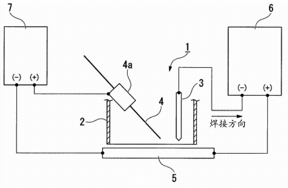
[0047] figure 1 It is a schematic configuration diagram showing an example of a gas welding apparatus provided with a welding torch used in the hybrid welding method of the present invention. exist figure 1 In , reference numeral 1 denotes a welding torch (welding torch for hybrid welding). The welding torch 1 generally includes: a nozzle main body 2 composed of a cylindrical member; a rod-shaped tungsten electrode 3 arranged on the leading side with respect to the welding direction in the nozzle main body 2; and a welding wire 4 arranged inside the nozzle main body 2. On the backward side relative to the welding direction; and a contact piece 4a for energizing the welding wire 4 . Moreover, the welding torch 1 has a single structure, and only one kind of shielding gas is used (illustration omitted).

[0048] The nozzle body 2 of the welding torch 1 is connected to a shielding gas supply source (not shown) that stores a shielding gas. The shielding gas from the shielding...


PUM


Abstract

Provided is a complex weld method that is able to increase arc stability and to improve weld speed and work efficiency. The disclosed complex weld method generates a tungsten inert gas (TIG) arc on the side ahead of the weld direction and a metal inert gas (MIG) arc on the side behind and welds a base metal. Provided is a complex weld method characterised by a TIG current set higher than the MIG current and by an absolute value of the separation between the point of intersection of the base metal and the TIG electrode central axis and the point of intersection between the surface of the base metal and the MIG electrode central axis of 4 mm or less.

Description

technical field [0001] The invention relates to a composite welding method and a welding blowpipe for composite welding. Background technique [0002] TIG (Tungsten Inert Gas Welding) welding, which generates an arc between a non-consumable tungsten electrode and an object to be welded in an inert gas atmosphere, is widely used because it can obtain high-quality welds. However, compared with other welding methods MAG (Metal Active Gas welding) welding and MIG (Metal Inert Gas welding) welding, TIG welding has slow welding speed and welding operations. The problem of low efficiency. [0003] On the other hand, the MAG welding method is performed in an active gas atmosphere, and the MIG welding method is performed in an inert gas atmosphere, and each is a welding method in which an arc is generated between a consumable wire electrode and an object to be welded. As described above, the MAG welding method and the MIG welding method are superior in work efficiency compared with...

Claims


Application Information

Patent Timeline
Patent Type & Authority Applications(China)
IPC IPC(8): B23K9/00B23K9/16B23K9/167B23K9/173B23K9/29
CPCB23K35/38B23K9/16B23K9/167B23K9/173B23K35/383B23K9/29B23K28/02
Inventor 金丸周平佐佐木智章佐藤丰幸
Owner NIPPON SANSO CORP
Why Eureka
Try Eureka