
On-line regeneration system and method of flue gas denitration catalyst

A denitrification catalyst and regeneration system technology, applied in the field of online regeneration system of flue gas denitrification catalyst, can solve the problems of high consumption of regeneration medicine, high resistance of flue gas, high regeneration cost, etc., achieve low consumption of regeneration medium, improve work efficiency, and regenerate The effect of low cost

Active Publication Date: 2015-05-20
北京宝莱尔科技有限公司
View PDF5 Cites 1 Cited by
  • Summary
  • Abstract
  • Description
  • Claims
  • Application Information

AI Technical Summary

Problems solved by technology

Its shortcomings are: 1. The catalyst module is removed from the flue before regeneration and hoisted to the ground. After regeneration, it is hoisted into the flue and then installed and restored. The amount of work is huge; 2. Due to the limited capacity of the regeneration device, only A single module is regenerated one by one. Each module needs to be hoisted into and out of five pools to complete the entire regeneration process. The process switching of each module requires a lot of cumbersome valve operations; 3. The catalyst has limited strength and is easily broken after frequent handling, resulting in smoke after being put into operation. The air resistance is large or even unable to run; 4. The consumption of regenerative medicine is large, the regeneration cost is high, and the entire regeneration period is long, which cannot meet the requirements of timely commissioning of the boiler

Method used


Image

  • On-line regeneration system and method of flue gas denitration catalyst
  • On-line regeneration system and method of flue gas denitration catalyst
  • On-line regeneration system and method of flue gas denitration catalyst

Examples


Embodiment Construction

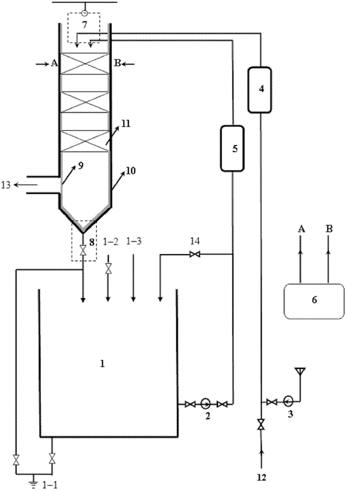
[0044] Such as figure 1 As shown, an on-line regeneration system for flue gas denitrification catalysts includes an external flue system, an internal flue system and connecting pipes; the external flue system and the internal flue system are connected through connecting pipes.

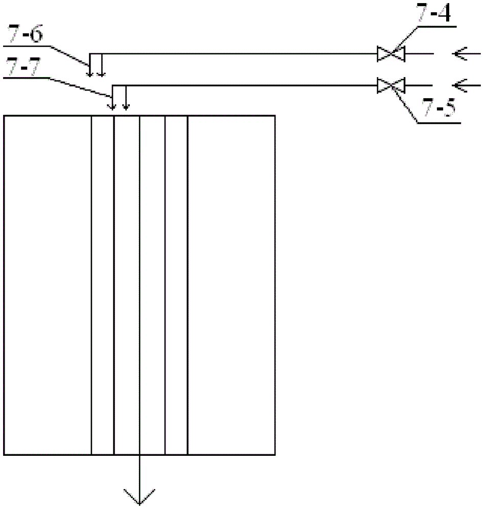
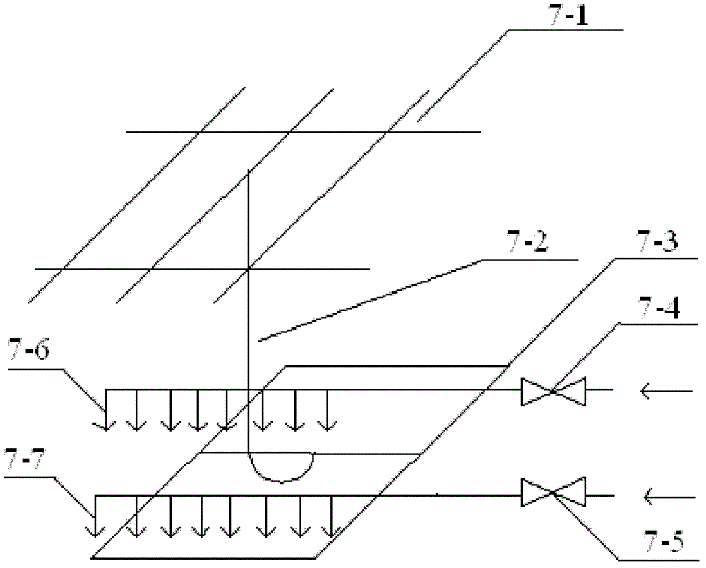
[0045] The system in the flue includes a distributor 7, a collector 8, and a protective film 9.

[0046] The collector 8 is installed at the bottom of the flue 10, establishes a liquid flow path with the distributor 7, and returns the liquid medium to the liquid storage tank 1 through the pipe.

[0047] When the flue gas denitration catalyst is regenerated online, the protective film 9 is fixed on the steel plate on the inner wall of the flue 10 by magnets to prevent the regeneration medium from corroding the inner wall of the flue and from polluting the regeneration medium by flue impurities. effect. Protective film 9 is plastic cloth.

[0048] The system outside the flue includes a liquid storage ...


PUM


Abstract

The invention provides an on-line regeneration system and a method of a flue gas denitration catalyst. The system comprises a gas duct external system, a gas duct internal system and a connection pipeline. The gas duct external system comprises a regeneration medium storage or generation component, a regeneration medium heating component and a generation medium conveying component. The gas duct internal system comprises a regeneration medium distribution component which is arranged in a gas duct and capable of moving to positions above any catalyst modules in the gas duct. A regeneration medium is conveyed into the regeneration medium distribution component in the gas duct to carry out catalyst regeneration steps including soot blowing, cleaning, drying and activation on the catalyst modules in the gas duct through regulation and starting and closing of the regeneration medium storage or generation component, the regeneration medium heating component and the generation medium conveying component in the gas duct external system, and the catalyst modules do not need to be moved out of the gas duct for regeneration. The on-line regeneration system and the method of the flue gas denitration catalyst avoid damage to the catalyst modules in the process of moving, simplify operation steps, reduce energy consumption, save cost and improve work efficiency.

Description

technical field [0001] The invention belongs to the technical field of flue gas treatment, and in particular relates to an online regeneration system and method for a flue gas denitrification catalyst. Background technique [0002] Recently, the country has promulgated a more stringent emission standard of air pollutants for thermal power plants GB13223-2011, which will be implemented from January 1, 2012. Among them, higher standards are set for the emission of nitrogen oxides in the air pollutants of thermal power plants. Therefore, starting from 2012, it is imperative to start the national denitrification market. [0003] In domestic and foreign thermal power plant boilers and other power boiler flue gas denitrification systems, more than 90% use the selective catalytic reduction method, that is, the SCR method. The flue gas denitrification catalyst used is a honeycomb type, plate type, and corrugated plate type solid with catalytic activity, which are vertically covered...

Claims


Application Information

Patent Timeline
Patent Type & Authority Patents(China)
IPC IPC(8): B01J38/48B01J38/04B01J38/00B01D53/86B01D53/56B01D53/48B01D53/64
Inventor 徐树元陶若虹任宏俊杨述芳
Owner 北京宝莱尔科技有限公司
Learn More