
Purification device of agriculture waste resource pyrolysis gasification system

A technology for pyrolysis gasification and agricultural waste, which is used in combustible gas purification, liquid scrubbing gas purification, combustible gas purification/reconstruction, etc. It can solve problems such as low purification efficiency and secondary pollution, and achieve less space occupation and improved utilization. The effect of reducing the production rate and manufacturing cost

Inactive Publication Date: 2013-06-05
LUOYANG JUNTENG ENERGY TECH
View PDF3 Cites 0 Cited by
  • Summary
  • Abstract
  • Description
  • Claims
  • Application Information

AI Technical Summary

Problems solved by technology

[0009] The purpose of the present invention is to overcome the defects of existing gas purification and purification equipment, and provide a new structure of purification and purification equipment in the pyrolysis gasification system of agricultural waste resources. The technical problem to be solved is to overcome the existing gas The purification efficiency of purification equipment is low, and it is easy to cause defects such as secondary pollution. Creating a purification and purification equipment in the pyrolysis gasification system of agricultural waste resources can quickly and efficiently purify the gas, and effectively remove moisture and impurities in the gas. It is very suitable for practical

Method used


Image

  • Purification device of agriculture waste resource pyrolysis gasification system
  • Purification device of agriculture waste resource pyrolysis gasification system
  • Purification device of agriculture waste resource pyrolysis gasification system

Examples


Embodiment Construction

[0038] In order to further explain the technical means and effects of the present invention to achieve the intended purpose of the invention, the following in conjunction with the accompanying drawings and preferred embodiments, the specific details of the purification and purification equipment in the agricultural waste resource pyrolysis gasification system proposed according to the present invention Embodiments, structures, features and effects thereof are described in detail below.

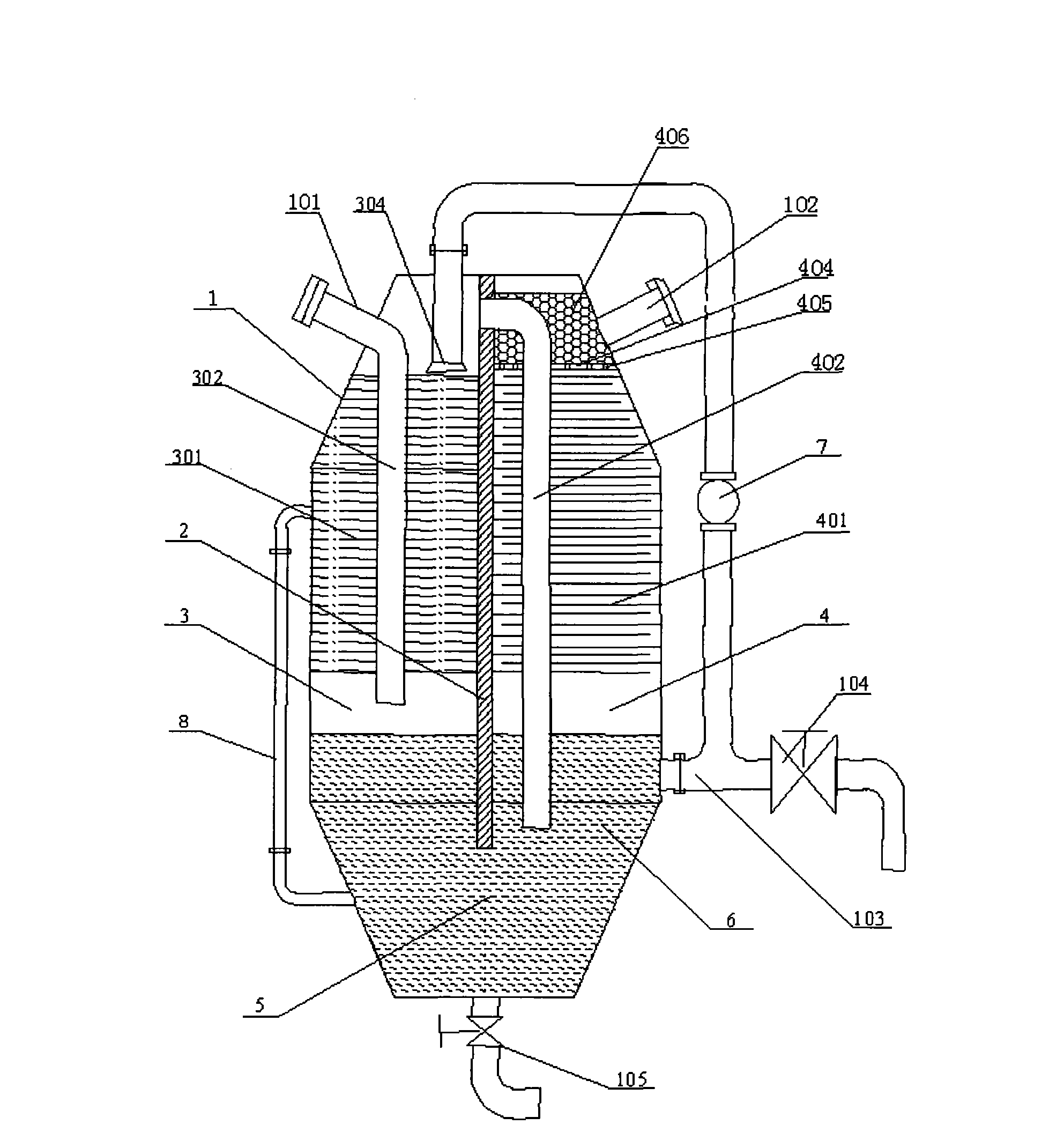
[0039] The purification and purification equipment in the pyrolysis and gasification system of agricultural waste resources includes a closed container 1, the size and shape of which can be set as required. The container 1 is provided with an air inlet 101 and an air outlet 102. After the mixed gas produced by the gasification system is condensed, the gas is pressed into the purification equipment from the air inlet 101 by the gas delivery equipment, and then flows out from the air outlet 102 f...


PUM


Abstract

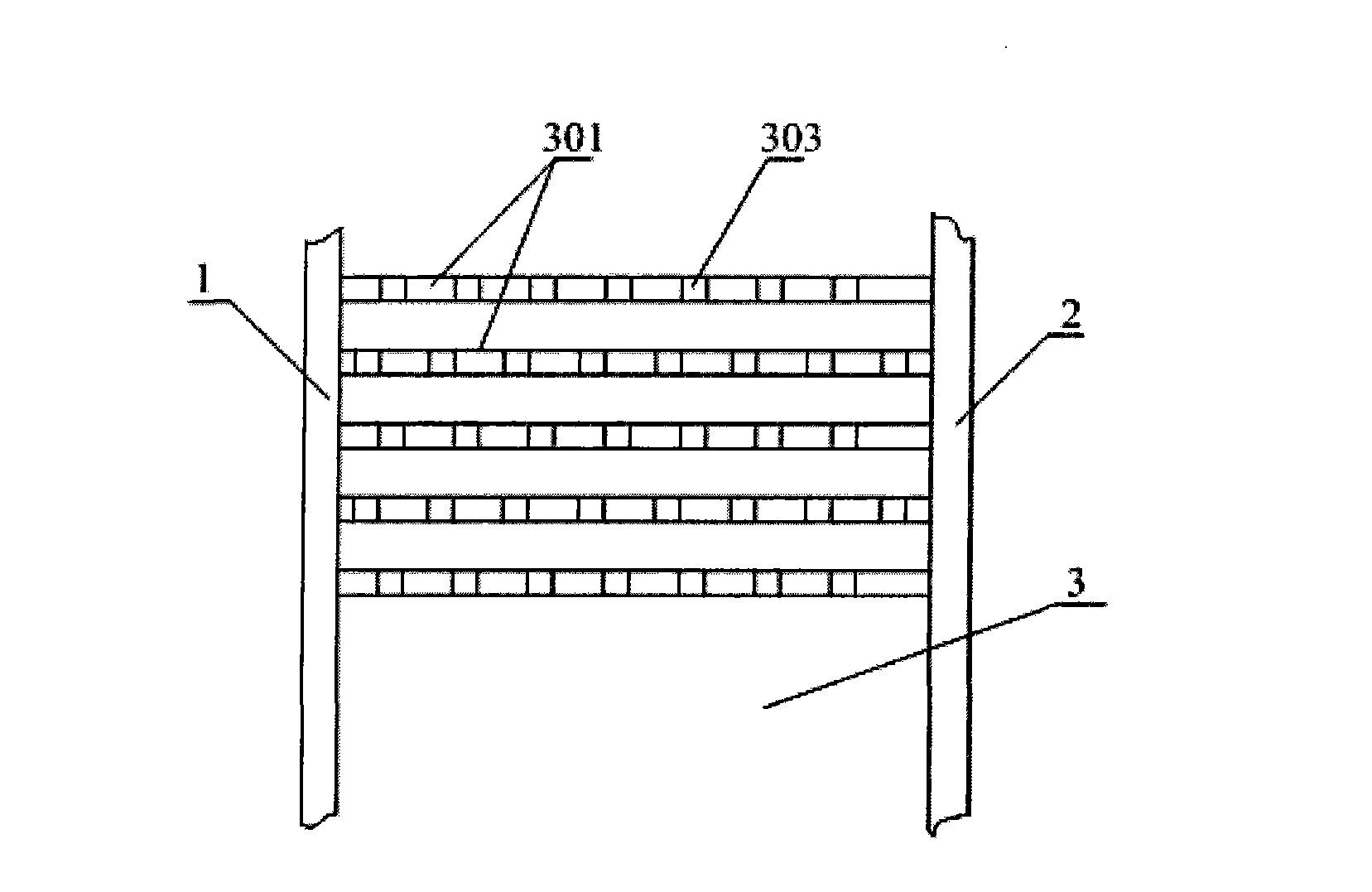
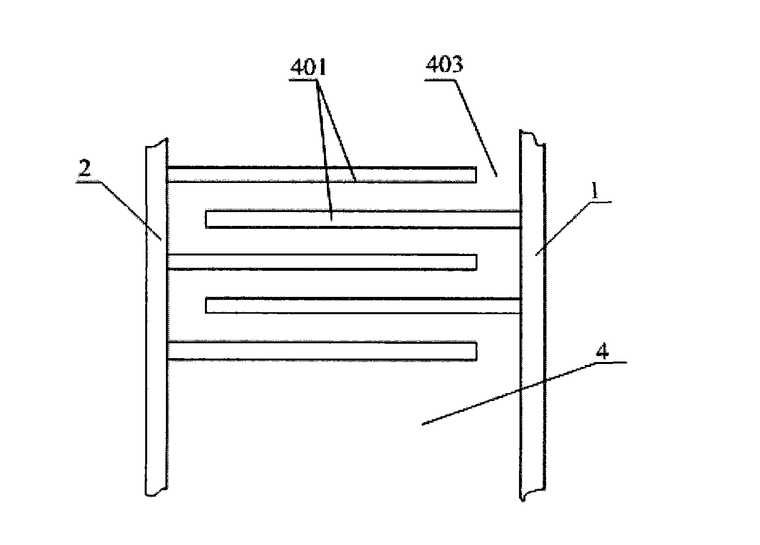
The invention relates to a purification device of an agriculture waste resource pyrolysis gasification system. An internal vertical clapboard divides a container into a leaching chamber and a gas-liquid separation chamber, an air inlet and an air outlet are respectively formed in the top of the leaching chamber and the top of the gas-liquid separation chamber, the leaching chamber is communicated with the gas-liquid separation chamber through a purification solvent flowing port, the container is loaded with a purification solvent, a spray header of the leaching chamber is communicated with the bottom of the container through a delivery pump, flow distribution plates are arranged in the leaching chamber, baffle plates are arranged in the gas-liquid separation chamber, the air inlet is connected to the lower portion of a bottom flow distribution plate through an air guide pipe, one end of an air delivery pipe in the gas-liquid separation chamber is communicated with the upper portion of the leaching chamber, and the other end of the air delivery pipe is arranged in the purification solvent. Air flowing ports in two adjacent baffle plates are respectively formed in two sides of the gas-liquid separation chamber. Functions such as leaching, bath washing, gas-liquid separation, counterseal and filtering are combined as a whole through a simple structure mode, the device is compact in structure and small in space usage, and the gas is separated from liquid particles through the baffle plates.

Description

technical field [0001] The invention relates to a gas purification and purification equipment in the utilization equipment of waste resources such as industrial organic solid waste and agricultural biomass waste, in particular to a pyrolysis gasification system of agricultural waste resources mainly composed of crop straws Purification and purification equipment. Background technique [0002] my country is a large agricultural country, and a large amount of biomass resources such as crop stalks and chaff residues are produced in agricultural production and agricultural product processing. Traditional utilization methods are mainly used as household energy, feed, fertilizer, industrial raw materials and construction materials. With the modernization of agricultural technology and the rapid development of agricultural economy, the rural living standards have been greatly improved and the way of life and production has changed abruptly. Such as coal, liquefied petroleum gas, ...

Claims


Application Information

Patent Timeline
Patent Type & Authority Applications(China)
IPC IPC(8): C10K1/10C10K1/12C10K1/00C10K1/08
Inventor 周仁福周强王韵涵陶然
Owner LUOYANG JUNTENG ENERGY TECH
Learn More