Internal leakage quantity detection device of hydraulic valves

A detection device and a technology for internal leakage, which are used in measurement devices, fluid pressure actuation devices, fluid tightness testing, etc. Human factors have great influence and other problems, and achieve the effect of high flexibility, high degree of automation and high sensitivity

Inactive Publication Date: 2013-06-05
ZHEJIANG UNIV
View PDF8 Cites 12 Cited by
  • Summary
  • Abstract
  • Description
  • Claims
  • Application Information

AI Technical Summary

Problems solved by technology

At present, the internal leakage test method of hydraulic valves is to manually record the number of drops of leakage liquid, and then convert it into milliliters, or collect it with a measuring cup for measurement. This test method is greatly affected by human factors and low test efficiency. The disadvantage is that it is difficult to meet the requirements of large-scale automatic quality inspection of hydraulic valves; the second is to measure the flow value by the flow sensor, and then calculate the leakage value, but the problem with this method is that the current flow sensor is used in micro and small flow It is difficult to measure or the accuracy of measurement is very low, which cannot meet the requirements of large measuring range and high measurement accuracy.

Method used


Image

  • Internal leakage quantity detection device of hydraulic valves
  • Internal leakage quantity detection device of hydraulic valves
  • Internal leakage quantity detection device of hydraulic valves

Examples


Embodiment Construction

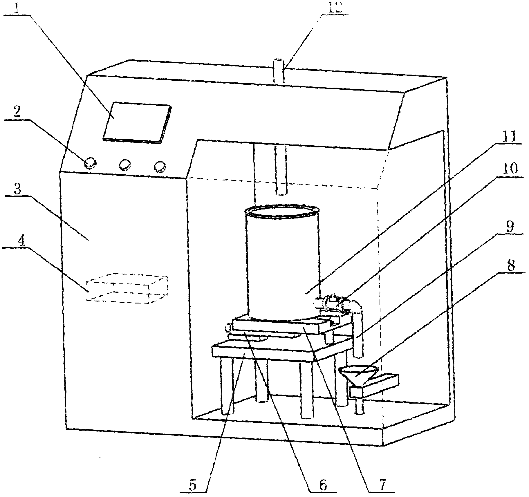
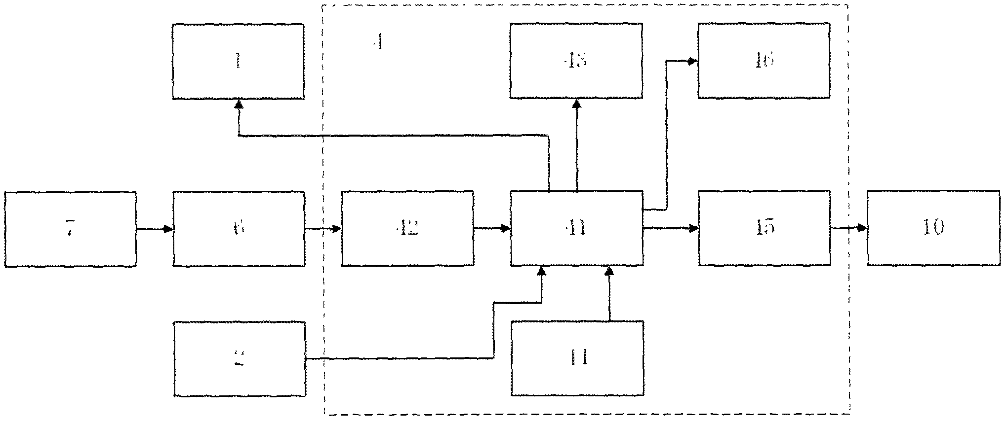
[0017] A schematic diagram of the product structure of an internal leakage detection device for a hydraulic valve of the present invention is as follows: figure 1 As shown, including test bench (3), bracket (5), container (11), oil inlet pipe (12), oil outlet pipe (9), funnel (8), load cell (7), transmitter (6) ), a single-chip microcomputer system (4), a display module (1), a two-position two-way electromagnetic reversing valve (10) and a button (2). The load cell (7) and the transmitter (6) are placed on the bracket (5), the load cell (7) is connected with the transmitter (6), and the transmitter can be of type XL-A2P; When the container (11) is placed on the bracket (5), the weighing sensor (7) and the transmitter (6) can realize the weighing of the container (11) and convert it into an electrical signal; there is an outlet at the bottom of the container (11). The oil port is connected to the oil outlet pipe (9). The oil pipe is equipped with a two-position two-way electro...


PUM


Abstract

The invention discloses an internal leakage quantity detection device of hydraulic valves. The internal leakage quantity detection device comprises a test bench (3), a support (5), a container (11), an oil inlet pipe (12), an oil outlet pipe (9), a funnel (8), a weighing sensor (7), a transmitter (6), a single-chip microcomputer system (4), a display module (1), a two-position two-way magnetic exchange valve (10) and a button (2). The inlet of the container enables leaked hydraulic oil leaked inside tested hydraulic valves to be stored inside the container (11) which is placed on the weighing sensor (7), the weighing sensor (7) and the transmitter (6) are placed on the support (5), weight of the leaked oil is converted into an electric signal through the weighing sensor (7) and the transmitter (6), the electric signal is converted into a digital signal through analog to digital (A/D) conversion, the digital signal is input into a single chip microcomputer and converted into internal leakage quantity through the single chip microcomputer, and the internal leakage quantity is displayed through the display module (1). The container (11) is specially provided with an outlet controlled by the magnetic exchange valve (10) to prevent the hydraulic oil from overflowing out of the container (11) during a measurement process, actual capacity of the container is measured through the single chip microcomputer, once the actual capacity exceeds the threshold value, measurement is stopped, the magnetic exchange valve (10) is opened through a relay, and the hydraulic oil inside the container (11) is discharged. The internal leakage quantity detection device measures the internal leakage quantity of hydraulic valves in an automatic weighing mode, can expand measurement range, can automatically measure minute leakage quantity, and can provide data basis for comprehensive assessment and performance improvement of batch quality of hydraulic valves.

Description

technical field [0001] The invention relates to the field of hydraulic valve testing, in particular to an internal leakage detection device of a hydraulic valve. Background technique [0002] Hydraulic transmission is a transmission method that uses liquid as a working medium to transmit energy and control. It is a widely used technology in industrial and agricultural production. The level of hydraulic transmission technology has become an important symbol of a country's industrial development level. Hydraulic valves are components used in hydraulic systems to control the pressure, flow and direction of liquids, including pressure control valves, flow control valves and directional control valves. The quality inspection of hydraulic valves is of great significance to ensure the accuracy, rapidity and stability of the entire hydraulic system. Before leaving the factory, each hydraulic valve must be strictly tested for its parameters by various means to check whether its perf...

Claims


Application Information

Patent Timeline
Patent Type & Authority Applications(China)
IPC IPC(8): F15B19/00
CPCG01M3/2876
Inventor 余忠华陆彬
Owner ZHEJIANG UNIV
Why Eureka
Try Eureka