Micro-electromechanical system (MEMS) silicon microphone utilizing multi-hole signal operation instruction (SOI) silicon bonding and manufacturing method thereof

A technology of a silicon microphone and a manufacturing method, which is applied to electrostatic transducer microphones, sensors, electrical components, etc., can solve the problems of reducing yield, increasing costs, and complicating manufacturing processes, and achieves improved yield, low cost, and improved productivity. Effects of Sensitivity and Yield

Active Publication Date: 2013-06-05
华景科技无锡有限公司
View PDF4 Cites 39 Cited by
  • Summary
  • Abstract
  • Description
  • Claims
  • Application Information

AI Technical Summary

Problems solved by technology

However, the method of changing the structure of the vibrating film will

Method used


Image

  • Micro-electromechanical system (MEMS) silicon microphone utilizing multi-hole signal operation instruction (SOI) silicon bonding and manufacturing method thereof
  • Micro-electromechanical system (MEMS) silicon microphone utilizing multi-hole signal operation instruction (SOI) silicon bonding and manufacturing method thereof
  • Micro-electromechanical system (MEMS) silicon microphone utilizing multi-hole signal operation instruction (SOI) silicon bonding and manufacturing method thereof

Examples


Embodiment Construction

[0047] The present invention will be further described below in conjunction with specific drawings and embodiments.

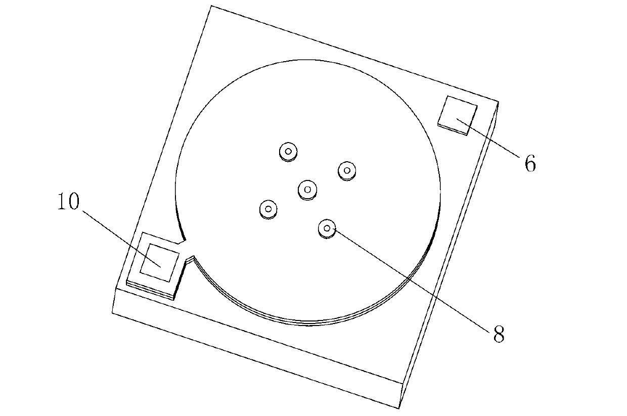
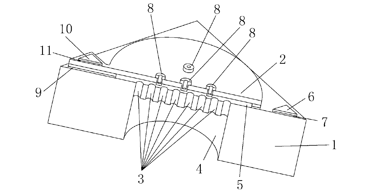
[0048] According to attached figure 1 ~ attached Figure 18 , the present invention includes a porous back plate silicon base 1, a single crystal silicon diaphragm 2, an acoustic hole 3, a back cavity 4, an air gap (plate spacing) 5, a back plate metal electrode 6, a back plate polysilicon 7, a small Protruding column 8 , insulating medium layer (ie silicon oxide layer) 9 , diaphragm metal electrode 10 , diaphragm polysilicon 11 .

[0049] According to attached image 3 , the MEMS silicon microphone of the present invention includes a porous back plate, a single crystal silicon diaphragm 2 located on the back plate and a support for the single crystal silicon diaphragm. In the present invention, the back plate includes a porous back plate silicon base 1 , and the porous back plate silicon base 1 is provided with an acoustic hole 3 and a back cavity 4 . The ...


PUM

PropertyMeasurementUnit
Thicknessaaaaaaaaaa

Abstract

The invention provides a micro-electromechanical system (MEMS) silicon microphone utilizing multi-hole signal operation instruction (SOI) silicon bonding and a manufacturing method thereof. The MEMS silicon microphone comprises a multi-hole back pole plate silicon substrate and a single crystal silicon vibrating diaphragm placed above the multi-hole back plate silicon substrate. The MEMS silicon microphone is characterized in that the multi-hole back plate silicon substrate and the single crystal silicon vibrating diaphragm serve as two pole plates of a microphone capacitor and are integrated in a bonding mode through a silicon bonding process. The multi-hole back pole plate silicon substrate is provided with a back pole plate metal electrode, a sound aperture and a back cavity, the single crystal silicon vibrating diaphragm is provided with a metal electrode and a small protruded column, and the vibrating diaphragm electrode and the back pole plate respectively serve as output signal leading-out ends of two pole plates of the microphone capacitor to be used for being in electric connection with a complementary metal oxide semiconductor (CMOS) signal amplifying circuit. The single crystal silicon vibrating diaphragm is supported by a silicon oxide layer to be suspended above the multi-hole back plate silicon substrate, and an air gap exists between the single crystal silicon vibrating diaphragm and the multi-hole back plate silicon substrate, and the multi-hole back plate silicon substrate, the single crystal silicon vibrating diaphragm and the air gap form a capacitance structure. The MEMS silicon microphone utilizing multi-hole SOI silicon bonding and the manufacturing method thereof are simple in process, high in product sensitivity, good in consistency and high in yield rate.

Description

technical field [0001] The invention relates to a capacitive silicon microphone and a preparation method thereof, in particular discloses a MEMS silicon microphone using porous SOI silicon-silicon bonding, which belongs to the technical field of silicon microphones. Background technique [0002] Microphones can convert human voice signals into corresponding electrical signals, and are widely used in mobile phones, computers, telephones, cameras and video cameras, etc. The traditional electret condenser microphone uses Teflon as the vibration film, which cannot withstand the high temperature of nearly 300 degrees in the reflow soldering process of the printed circuit board, so it can only be separated from the assembly of the integrated circuit and assembled by hand alone, which greatly increases the production cost . [0003] The development of MEMS (Microelectromechanical Systems) technology and process in the past three decades, especially the development of MEMS technolo...

Claims


Application Information

Patent Timeline
IPC IPC(8): H04R19/04H04R31/00
Inventor 缪建民
Owner 华景科技无锡有限公司
Why Eureka
Try Eureka