Moving field vacuum coating magnetron sputtering source

A vacuum coating and magnetron sputtering technology, applied in the field of metallurgy, can solve the problems of unsuitable small magnetron sputtering sources, low target utilization rate, poor sputtering uniformity, etc. Improved uniformity and uniform particle distribution

Inactive Publication Date: 2013-06-12
CHANGCHUN KENA OPTOELECTRONICS TECH
View PDF5 Cites 3 Cited by
  • Summary
  • Abstract
  • Description
  • Claims
  • Application Information

AI Technical Summary

Problems solved by technology

[0006] The purpose of the present invention is to provide a dynamic magnetic field vacuum coating magnetron sputtering source, which is used to produce products or devices with vacuum deposited layers, and overcomes the problem of target material and magnet in the prior art due to the relatively fixed positions of the targe

Method used


Image

  • Moving field vacuum coating magnetron sputtering source
  • Moving field vacuum coating magnetron sputtering source
  • Moving field vacuum coating magnetron sputtering source

Examples


Embodiment Construction

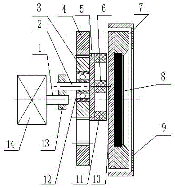
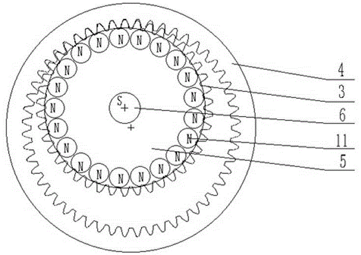
[0018] refer to figure 1 , figure 2 , the present invention includes a target substrate 10 with the front in a vacuum deposition chamber, a target pressure ring 7 connected to the target substrate, a sheet-shaped target material 8 welded or fixed on the front of the target substrate by a pressure ring, covering the circumferential side of the target substrate and The shielding ring 9 on the front of the target substrate other than the target material, the magnetic steel substrate 5 arranged on the back of the target substrate, the inner magnetic steel 6 installed on the magnetic steel substrate facing the center of the target substrate side, and the outer magnetic steel at the circumferential position 11. The outer magnet 11 and the inner magnet 6 are respectively composed of a plurality of magnet bodies, and the magnetic poles of the outer magnet 11 and the inner magnet 6 are opposite. The diameter of the magnetic steel substrate 5 is greater than the radius of the target m...


PUM


Abstract

The invention discloses a moving field vacuum coating magnetron sputtering source which comprises a target base plate, a platy target welded or fixed on the front of the target base plate by a pressure ring, a shielding ring, a magnetic steel base plate and inner magnetic steel and outer magnetic steel mounted on the magnetic steel base plate. An improvement is as follows: the diameter of the magnetic steel base plate is greater than the radius of the target and less than the diameter of the target; the axis of the magnetic steel base plate deviates from the axis of the target base plate; the magnetic steel base plate is fixed on a side surface of a spur gear; a gear ring meshed with the spur gear is mounted on a rack of a coating machine; a motor located on the rear side of the spur gear is mounted on the rack; a crank handle is fixed on a power output shaft of the motor; a gear shaft is mounted on the crank handle; and the power output shaft of the motor and the gear ring are coaxially arranged with the target base plate. The moving field vacuum coating magnetron sputtering source disclosed by the invention has the positive effects that a toroidal magnetic field with revolution and autorotation is obtained and used for scanning each position of the target so that a larger area of the target is uniformly sputtered and etched. The utilization rate of the target is high, and the coating is uniform.

Description

technical field [0001] The invention belongs to the field of metallurgy, and in particular relates to a vacuum magnetron sputtering method for depositing and coating equipment on the surface of a material. Background technique [0002] With the development of science and technology, more and more products and devices are prepared by vacuum deposition, especially the magnetron sputtering technology is widely used for its high output and good film quality. At present, magnetron sputtering technology is widely used in high-tech fields such as integrated circuits, liquid crystal displays, thin-film solar cells and LEDs. The magnetron sputtering source is its key component. Circular magnetron sputtering sources are often used in scientific research experiments and the production of small devices. Because the sputtering target is relatively expensive, the small magnetron sputtering source brings another technical problem: how to make the sputtering etching track of the target on...

Claims


Application Information

Patent Timeline
IPC IPC(8): C23C14/35
Inventor 刘星宇
Owner CHANGCHUN KENA OPTOELECTRONICS TECH
Why Eureka
Try Eureka