Modularized cage barrier rotor and stator self excitation synchronous motor and control method thereof

A rotor-stator and synchronous motor technology, applied in electronic commutation motor control, synchronous generator, motor generator control, etc., can solve the problem of poor coupling effect of two sets of stator windings, complicated manufacturing process, uncertain parameter changes and problems Problems such as large disturbance impact

Active Publication Date: 2013-06-12
张凤阁
View PDF6 Cites 8 Cited by
  • Summary
  • Abstract
  • Description
  • Claims
  • Application Information

AI Technical Summary

Problems solved by technology

The radial laminated salient pole reluctance rotor with cogging is easy to process, but the coupling effect on the two sets of stator windings is not good; the axial laminated reluctance rotor has strong coupling ability, but the manufacturing process is complicated. Difficult to use in AC motors
In addition, the control system of conventional AC motors with double sets of windings placed on the stator is greatly affected by uncertain parameter changes and disturbances, and has disadvantages such as poor anti-interference ability

Method used


Image

  • Modularized cage barrier rotor and stator self excitation synchronous motor and control method thereof
  • Modularized cage barrier rotor and stator self excitation synchronous motor and control method thereof
  • Modularized cage barrier rotor and stator self excitation synchronous motor and control method thereof

Examples


Embodiment Construction

[0072] The present invention is described in detail below in conjunction with accompanying drawing:

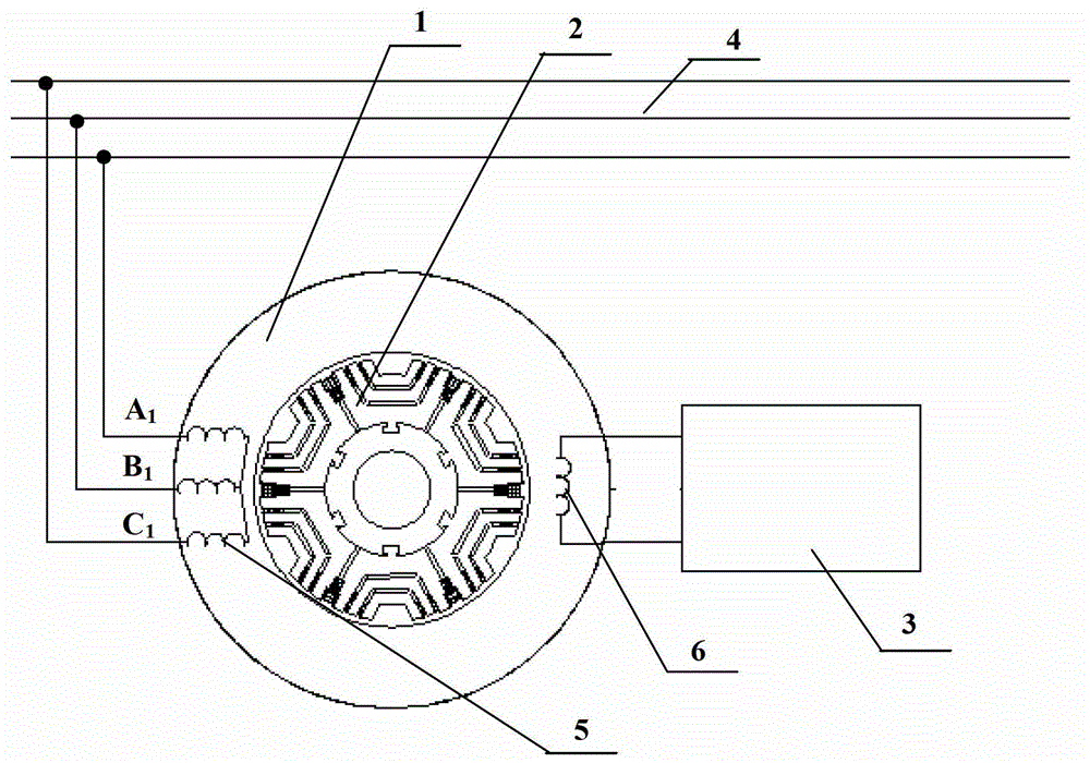
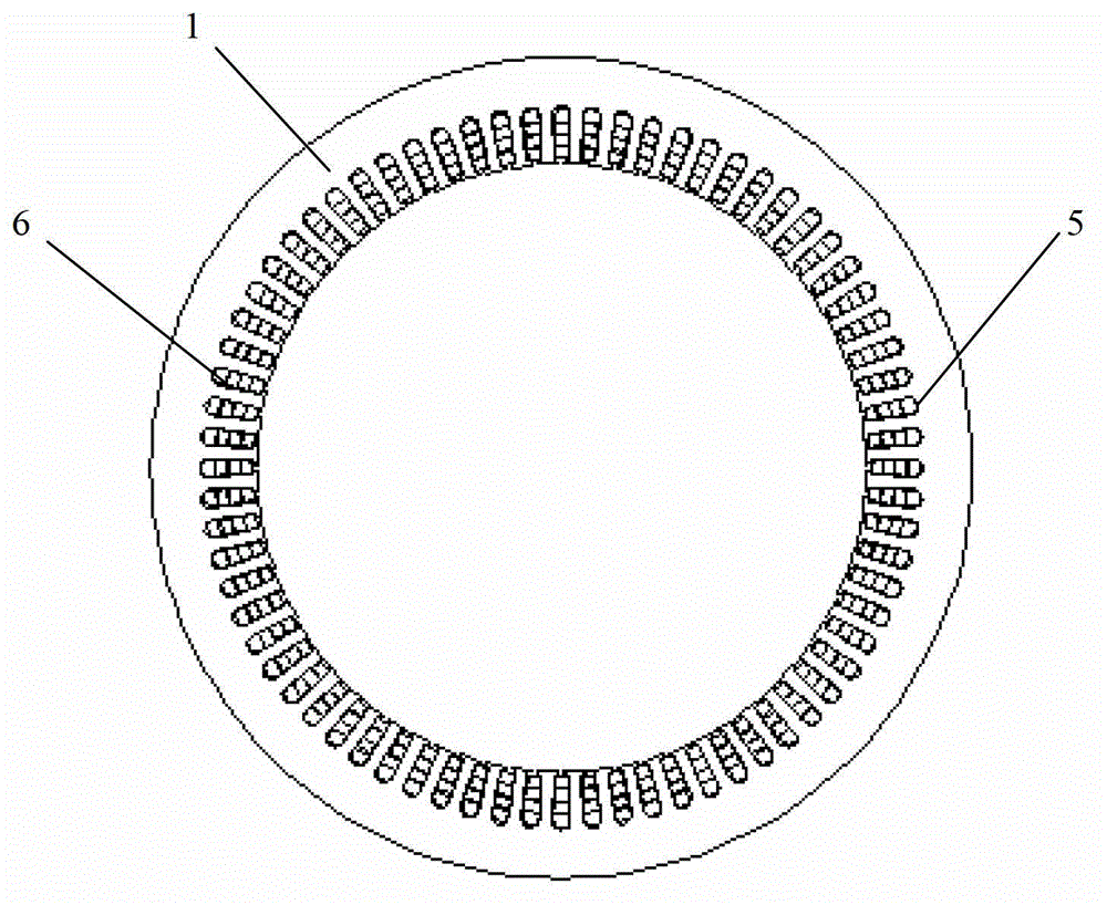
[0073] figure 1 It is a schematic structural diagram of the modular cage rotor stator self-excited synchronous motor system of the present invention, the system mainly includes a stator 1, a rotor 2, and a bidirectional inverter 3, wherein three-phase symmetrical armature windings 5 ​​and 2q of 2p poles are placed on the stator 1 The poles of the single-phase symmetrical field winding 6, the poles of the armature winding 5 and the field winding 6 are also interchangeable, and all satisfy 2p-2q≥4, which can maximize the electromagnetic coupling of two sets of stator windings with different pole numbers. The electromagnetic coupling between two sets of stator windings with different numbers of poles is maximized. The armature winding 5 is connected to the grid 4 , and the field winding 6 is connected to the controllable DC power supply 3 . By controlling the DC power supply 3 ...


PUM


Abstract

The invention relates to a synchronous motor, which is characterized in that a set of 2p electrode three-phase armature winding and a set of 2q electrode single-phase excitation winding are placed on a stator, the stator self excitation is realized on the power supply of the excitation winding, a rotor is split into the rotor with the convex electrode form by cage barrier modules in the circumferential direction, each cage barrier rotor module is connected with a sleeve made of non-magnetic conducting materials through a positioning groove, the cage barrier rotor modules are provided with a plurality of radial trapezoidal grooves, each trapezoidal groove is provided with a plurality of different step groove widths in the radial direction, short circuit cage strips are placed into the trapezoidal grooves, the edges of the adjacent cage barrier rotor modules are step-shaped notches, public trapezoidal grooves are formed after the split joint, the gap depth at the bottoms of the grooves reaches the outer surface of the sleeve, and public cage strips are placed into the grooves. The invention aims at providing the novel modularized cage barrier rotor and stator self excitation synchronous motor structure with the advantages that the processing and the manufacture are convenient, and the coupling capability on the two sets of windings of the stator realizes the maximization, so high power density and good steady and dynaic performance are realized.

Description

Technical field: [0001] The invention relates to a synchronous motor, in particular to a modular cage barrier rotor stator self-excited synchronous motor and a control method thereof. The motor can be operated as a motor or as a generator. Background technique: [0002] The stator of the modular cage rotor stator self-excited synchronous motor includes three-phase symmetrical armature windings with 2p poles and single-phase symmetrical field windings with 2q poles (or three-phase symmetrical armature windings with 2q poles and single-phase symmetrical armature windings with 2p poles excitation winding), and satisfy 2p-2q≥4, the coupling between the two sets of windings is by p r =p+q is achieved by a specially designed rotor for poles, so this type of motor does not need to install brush slip rings, and can realize electromechanical energy conversion through the interaction between the magnetic field of the excitation winding and the magnetic field of the armature winding, ...

Claims


Application Information

Patent Timeline
Patent Type & Authority Applications(China)
IPC IPC(8): H02K19/12H02K19/14H02K19/28H02P21/00
Inventor 张凤阁
Owner 张凤阁
Why Eureka
Try Eureka