
Flexible matrix display device for electrogenerated luminescence of inorganic powders

A matrix display and inorganic powder technology, applied in the field of flat-panel electroluminescent display devices, can solve problems such as low yield, complicated electrode preparation, and inability to scale production

Inactive Publication Date: 2013-06-12
SHANGHAI KERUN PHOSPHOR TECH
View PDF5 Cites 12 Cited by
  • Summary
  • Abstract
  • Description
  • Claims
  • Application Information

AI Technical Summary

Problems solved by technology

The disadvantage is that the electrode preparation is complicated, the yield is low, and it cannot be mass-produced. At the same time, only the complex and high-cost passive drive mode can be used

Method used


Image

  • Flexible matrix display device for electrogenerated luminescence of inorganic powders
  • Flexible matrix display device for electrogenerated luminescence of inorganic powders
  • Flexible matrix display device for electrogenerated luminescence of inorganic powders

Examples


Embodiment

[0050] Choose a polyimide copper foil film with a thickness of 0.05 mm, the pixel element is 1X1 mm, and the overall area is 100X100 mm.

[0051] Use barium titanate mixed with fluorine paint glue, use screen printing process to print the media layer, and dry at 100 degrees.

[0052] Use D502 luminescent material mixed with fluorine paint glue, use screen printing process to print the luminescent layer, and dry at 100 degrees.

[0053] Use ITO and PET films to make transparent conductive layers and transparent panels. Use silver glue as a transparent conductive layer electrode.

[0054] Red, blue, and green fluorescent color coatings can be printed on the outside of the transparent transparent panel, which respectively correspond to independent light-emitting pixel elements.

[0055] Using active high-voltage chips to drive its work, flexible matrix inorganic electroluminescent flat panel displays can display colorful text patterns and images.


PUM

PropertyMeasurementUnit
thicknessaaaaaaaaaa
particle sizeaaaaaaaaaa

Abstract

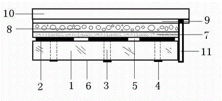
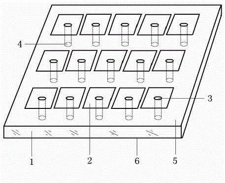
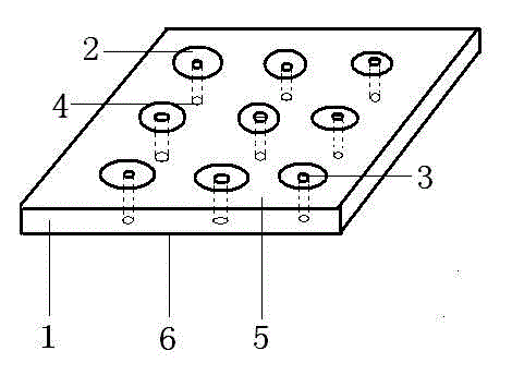
The invention discloses a flexible matrix display device for electrogenerated luminescence of inorganic powders. The flexible matrix display device comprises a flexible substrate, flexible substrate conduction holes, a matrix back electrode layer, a dielectric layer, a luminescent layer, a transparent conduction layer, a transparent panel, a matrix back electrode and a transparent conduction layer electrode. The flexible matrix display device is characterized in that the flexible substrate conduction holes are regularly distributed in the flexible substrate, and the flexible substrate conduction holes are connected with the matrix back electrode layer and the matrix back electrode; the matrix back electrode layer is sequentially provided with the dielectric layer, the luminescent layer, the transparent conduction layer and the transparent panel; the transparent conduction layer is connected with the transparent conduction layer electrode; and an active driving method is utilized, a matrix scanning circuit device is connected with the matrix back electrode to be controlled with a single-point electronic chip, the matrix scanning circuit device is driven by an electrical field to be luminescent, and a dynamic image combined with independent luminescent pixel elements is formed.

Description

technical field [0001] The invention belongs to the technical field of flat panel electroluminescence display devices application. Background technique [0002] As a terminal device of information technology, flat panel light-emitting display devices have been widely used in mobile phones, televisions, computers, and the like. At this stage, the new flat panel display technology is constantly pursuing technical indicators such as large, light, thin, and power-saving. At present, most flat panel displays are based on glass substrates, such as field emission displays (FED), liquid crystal displays (LCD), organic electroluminescent displays (OEL or OLED), and plasma displays (PDP). The disadvantages are that the glass is easily broken, the area is limited, the weight is large, the work is hot, it cannot be bent, the production cycle is long, and the cost is high. Existing electroluminescent displays are also based on glass, such as: inorganic thick-film electroluminescent dis...

Claims


Application Information

Patent Timeline
Patent Type & Authority Applications(China)
IPC IPC(8): H05B33/12
Inventor 郑岩边静宇孟立建费运启张永亮
Owner SHANGHAI KERUN PHOSPHOR TECH
Learn More