Selective catalytic reduction (SCR) metering injection pump urea crystal dissolving device

A technology of dissolving device and jet pump, which is applied to the separation of dispersed particles, chemical instruments and methods, separation methods, etc., can solve the problems of reductant clogging, reductant crystal accumulation, orifice clogging, etc., and achieves ingenious design and simple structure , easy maintenance effect

Inactive Publication Date: 2013-06-19
SUZHOU POWERGREEN EMISSION SOLUTION SYST
View PDF4 Cites 4 Cited by
  • Summary
  • Abstract
  • Description
  • Claims
  • Application Information

AI Technical Summary

Problems solved by technology

[0003] The SCR injection system is divided into airless system and air system. Among them, the air injection control system filters and atomizes the reducing agent, and then injects the reducing agent into the exhaust pipe through air assistance. In the air injection system In the internal mixing structure, a mixing chamber is often set up to pre-mix before the reducing agent is injected, that is, the high-speed air flow passes through the orifice on the side wall of the mixing chamber and the reducing agent injected into the mixing chamber is mixed with gas and liquid, as shown in the Chinese patent The gas control system disclosed in the patent with the announcement number CN201982159U and the name "Air-liquid Mixing Device of Urea Metering Pump in SCR System" has a mixing chamber and an orifice arranged tangentially. On the one hand, the mixing effect is good, and on the other hand, it can Provide injection pressure, however, due to the small diameter of the orifice on the side wall of the mixing chamber, it is easy to be blocked by the returning reducing agent
[0004] In order to prevent the orifice from cloggi

Method used


Image

  • Selective catalytic reduction (SCR) metering injection pump urea crystal dissolving device
  • Selective catalytic reduction (SCR) metering injection pump urea crystal dissolving device
  • Selective catalytic reduction (SCR) metering injection pump urea crystal dissolving device

Examples


Embodiment Construction

[0021] The technical solutions of the embodiments of the present invention will be clearly and completely described below in conjunction with the accompanying drawings of the present invention.

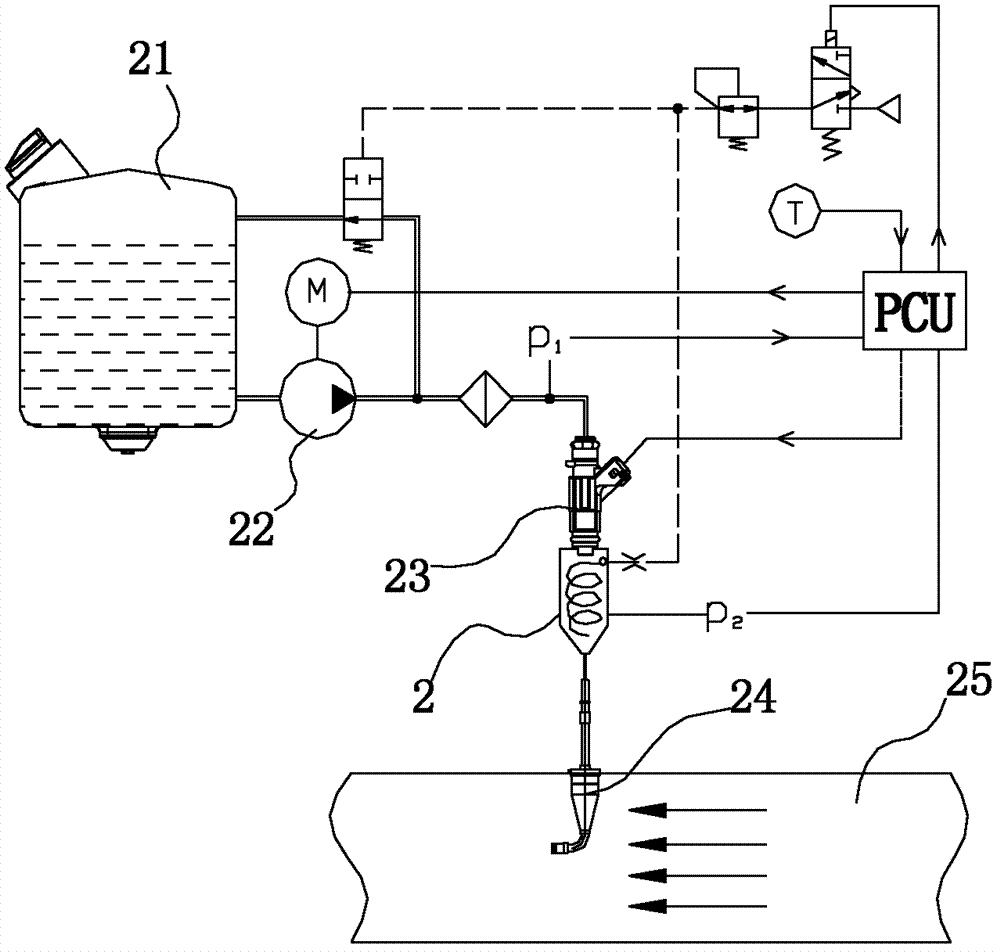
[0022] Such as figure 1 As shown, the SCR system using the technology of the present invention generally includes a liquid storage tank 21, a pumping device 22, a metering valve 23, a mixing chamber 2 and a nozzle 24 connected in series in sequence, and the pumping device 22 transfers the reducing agent from the liquid storage tank 21 The reductant is sent into the metering valve 23 and the mixing chamber 2 in sequence, and then the reducing agent is injected into the exhaust pipe 25 by the nozzle 24 to carry out catalytic reduction reaction, so as to achieve the effect of exhaust gas purification.

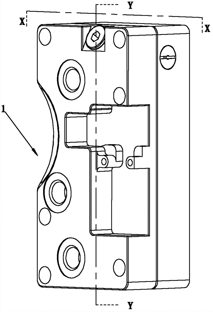
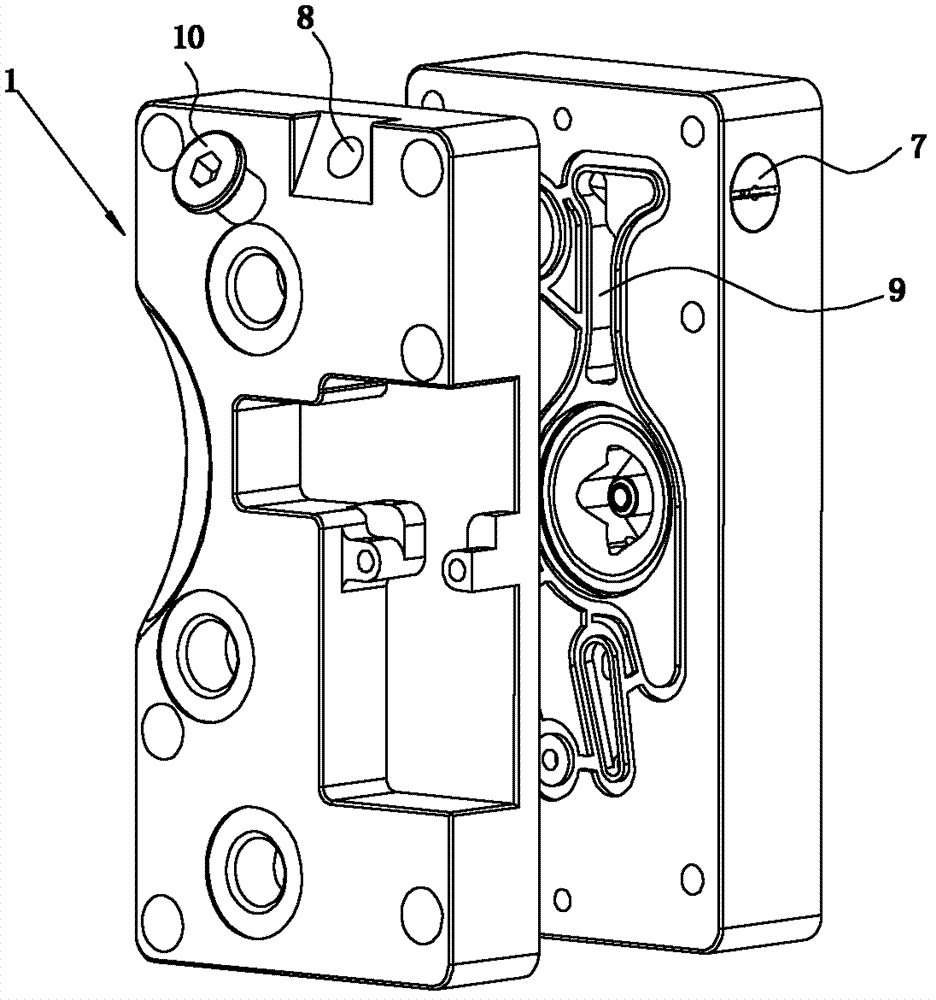
[0023] Figure 2-Figure 5 A preferred embodiment of the present invention is shown. The SCR metering jet pump urea crystal dissolving device of the present invention includes a pump body...


PUM


Abstract

The invention discloses a selective catalytic reduction (SCR) metering injection pump urea crystal dissolving device which comprises a pump body and a mixing cavity installed inside the pump body, the side wall of the mixing cavity is provided with an orifice, the pump body is further provided with a flow guide pipeline, at least one chamber is formed inside the pump body, the chamber is communicated with the orifice, one end of the flow guide pipeline is communicated with fluid, and the other end of the flow guide pipeline is communicated with the chamber. The SCR metering injection pump urea crystal dissolving device is simple in structure and ingenious in design, and only purified water is required to be injected into the flow guide pipeline to dissolve reducing agent crystal inside the pump body. Meanwhile, dirt inside the SCR metering injection pump urea crystal dissolving device can be washed away, atomized reducing agents are prevented from diffusing into an air cylinder cavity to cause blocking faults of the pump body, and maintenance is convenient.

Description

technical field [0001] The invention relates to a metering jet pump crystal dissolving technology in an SCR system, in particular to a urea crystal dissolving device for an SCR metering jet pump. Background technique [0002] With the promotion and implementation of the "National IV" and "National V" emission standards for motor vehicles in major cities and even the whole country, the SCR technology route has gradually matured, that is, the reducing agent (32.5% urea aqueous solution) is atomized and quantitatively sprayed into the exhaust pipeline , and through the SCR catalyst, the main harmful gas NO in the exhaust gas X It is converted into nitrogen and water and discharged to achieve the purpose of tail gas purification. [0003] The SCR injection system is divided into airless system and air system. Among them, the air injection control system filters and atomizes the reducing agent, and then injects the reducing agent into the exhaust pipe through air assistance. In ...

Claims


Application Information

Patent Timeline
IPC IPC(8): B01D53/90B01D53/56
Inventor 郝庆军
Owner SUZHOU POWERGREEN EMISSION SOLUTION SYST
Why Eureka
Try Eureka