
Water wheel power generation device

A hydroelectric power generation and water wheel technology, which is applied in wind power generation, engines, engine components, etc., can solve the problems of low utilization rate of water energy, large space occupation, no energy storage equipment, etc., and achieve high utilization rate of water energy, Beautify the building environment, easy to install and use

Active Publication Date: 2013-06-19
周登荣 +1
View PDF8 Cites 2 Cited by
  • Summary
  • Abstract
  • Description
  • Claims
  • Application Information

AI Technical Summary

Problems solved by technology

[0003] For example, the Chinese patent application with the application number 200710086447 and titled "Variable Speed ​​Hydrogenerator", the power generation system disclosed in this application is complicated to install and takes up a lot of space
Another example is the Chinese application with the application number 95235346.6 and the title "Hydraulic Generator", which discloses a hydroelectric power generation device. The above two structures are single water wheels, and there is a problem of low utilization rate of water energy, and they Without setting up energy storage equipment, the generated electricity cannot be reasonably utilized and controlled
The feedback of the speed of the water wheel is also very important for the operation of the generator and the control system of power generation and energy storage. The existing water wheel generators have not processed and utilized it

Method used


Image

  • Water wheel power generation device
  • Water wheel power generation device
  • Water wheel power generation device

Examples


Embodiment Construction

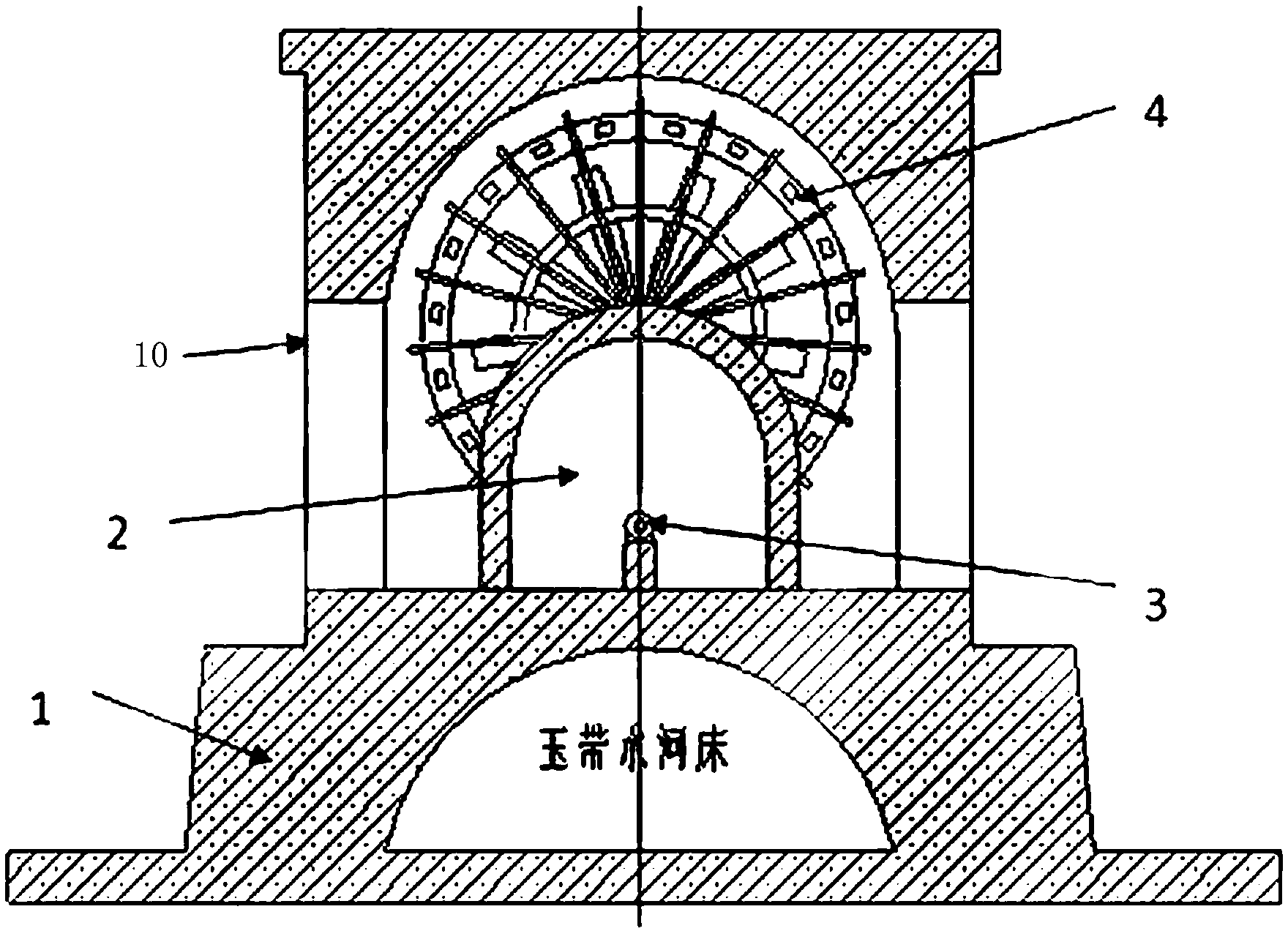
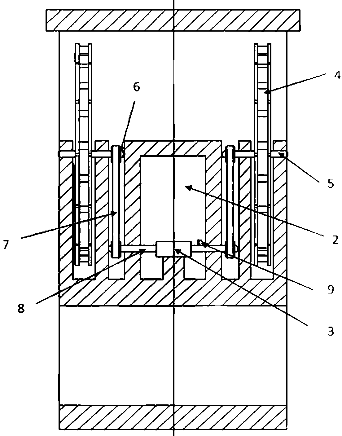
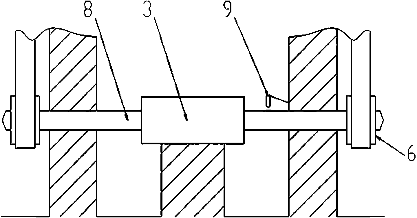
[0020] exist figure 1 and figure 2 In the preferred embodiment shown, the hydroelectric power generation device of the present invention includes a water wheel tower base 1, a generator machine room 2, a generator 3, a water wheel 4, rotating shafts 5 and 8, a belt 7 and a pulley 6, and a speed sensor 9 .

[0021] A generator machine room 2 is built on the tower base of the water wheel, and a generator 3 and a power generation and energy storage control system are arranged in the generator machine room. Pulleys 6 are respectively arranged at both ends of the rotating shaft connected to the generator, and a water wheel is fixed on the top of the machine room. Rotating shaft 5, one end of which passes through the water wheel 4, and the other end is fixed on the top of the concrete platform; the belt 7 connects the pulley of the water wheel rotating shaft 5 and the pulleys at the two ends of the motor rotating shaft 8.

[0022] The generator room in this embodiment can isolate...


PUM


Abstract

The invention relates to a water wheel power generation device which comprises a water wheel tower footing, a generator room, a generator, water wheels, a rotating shaft belt, a belt pulley and a power generation stored energy control system. The generator room is built on the water wheel tower footing, and the generator and the power generation stored energy control system are placed inside the generator room. Two water wheels are adopted to rotate to generate electricity, generated energy can be increased exponentially, and driving torque of the water wheels can be improved. A revolution speed transducer is placed on a rotating shaft of a motor, the revolution speed of the water wheels is monitored by the revolution speed transducer, the monitoring value is sent to the power generation stored energy control system which is used for judging working conditions of the generator, and therefore power supply and stored energy are distributed. The water wheel power generation device is placed on the periphery of a wind tower building and is combined with a wind tower power generation system, and the power sent out by the water wheel power generation device is used for driving a powerful blower. The water wheel power generation device overcomes the defects of the prior art, and has the advantages of being simple in structure, convenient to install and use and high in utilization rate of water. Not only is the building environment beautified, but also partial building power utilization loading is supplied with electricity.

Description

technical field [0001] The invention relates to a device for generating electricity by using hydropower, in particular to a hydroelectric power generation device arranged on the periphery of a wind tower building and used to drive a powerful blower. Background technique [0002] With the development of new energy sources, the comprehensive utilization of hydropower for power generation is of great significance. The hydroelectric power station uses the kinetic energy generated by the water flow to drive the generator set to generate electricity. The existing hydroelectric generator uses water to impact the water wheel, and the rotation of the water wheel drives the generator to generate electricity. [0003] For example, the Chinese patent application whose application number is 200710086447 and whose title is "Variable Speed ​​Hydroelectric Generator" discloses a power generation system that is complicated to install and takes up a lot of space. Another example is the Chine...

Claims


Application Information

Patent Timeline
Patent Type & Authority Applications(China)
IPC IPC(8): F03B13/00F03D9/00
CPCY02B10/30Y02B10/70Y02E10/72
Inventor 周登荣周剑
Owner 周登荣
Learn More