
Solar cell and corresponding electrode screen printing plate

A technology for solar cells and cells, applied in printing, printing presses, rotary printers, etc., can solve the problems of increasing the bending degree of cells, falling off of battery electrode busbars, reducing effective light area, etc., so as to reduce production costs. , The effect of reducing the probability of falling off and increasing the effective light area

Inactive Publication Date: 2013-06-26
KUN SHAN POWER STENCIL
View PDF5 Cites 9 Cited by
  • Summary
  • Abstract
  • Description
  • Claims
  • Application Information

AI Technical Summary

Problems solved by technology

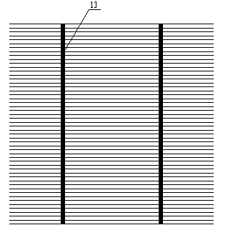
Although the main grid line of this structure has a good current collection effect, its contact area with the silicon plate is too large, which reduces the effective illumination area and reduces the conversion efficiency of solar energy; at the same time, the excessively large electrode and silicon (such as Ag- Si) compound area, which increases the bending degree of the battery sheet to a certain extent (the thermal expansion coefficient of the electrode metal material and the silicon sheet is different, after sintering and cooling, the battery sheet will appear bending phenomenon), the resulting stress is easy to cause the main electrode of the battery The grid line falls off; in addition, the cost of electrode raw materials (such as conductive silver paste) is relatively high, which is not conducive to mass production

Method used


Image

  • Solar cell and corresponding electrode screen printing plate
  • Solar cell and corresponding electrode screen printing plate
  • Solar cell and corresponding electrode screen printing plate

Examples


Embodiment 1

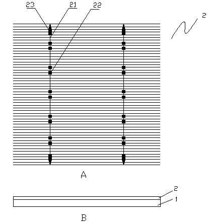
[0023] like figure 2 As shown, a kind of solar cell according to the present invention includes a cell substrate 1 (such as figure 2 B) and the electrode 2 printed on the substrate, the electrode 2 includes two main grid lines 21, the main grid lines 21 are linear, and the wire diameter is about 0.4 mm. There are 12 square nodes 22 and triangular nodes 23 for testing on each busbar 21, wherein there are 10 square nodes 22 on the busbar 21, and the side length of the square nodes is about 1.5mm. There are two triangular nodes 23 on the ends of the busbar 21, and the length of the base of the triangular nodes 23 is about 1.5 mm. The centerline of the busbar 21 bisects the node 22 and the node 23 equally.

[0024] According to another aspect of the present invention, the present invention also provides a screen for printing the above-mentioned solar cell electrode, the screen can be made of any material combined with any process, and the screen is provided with a The busbar ...

Embodiment 2

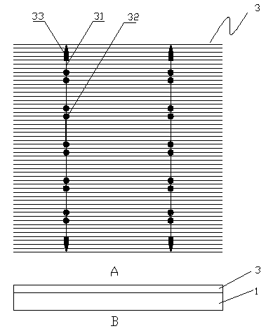
[0026] like image 3 As shown, a kind of solar cell according to the present invention includes a cell substrate 1 (such as image 3 B) and the electrode 3 printed on the substrate, the electrode includes two main grid lines 31, the main grid lines are linear, and the wire diameter is about 0.4 mm. The busbar 31 has 12 nodes for testing, wherein, there are 10 circular nodes 32 on the busbar 31, and the diameter of the circular node is about 1.5mm, and there are 2 nodes on the busbar 31 terminal. A triangular node 33, the length of the base side is about 1.5mm. The center line of the busbar 31 bisects the node 32 and the node 33 equally.

[0027] According to another aspect of the present invention, the present invention also provides a screen for printing the electrodes of the above-mentioned solar cells, which can be made of any material combined with any process, and the screen is provided with a main screen for forming the electrodes. Patterns of gridlines and nodes. Pr...


PUM

PropertyMeasurementUnit
Wire diameteraaaaaaaaaa
Diameteraaaaaaaaaa
Wire diameteraaaaaaaaaa

Abstract

The invention provides a solar cell. The solar cell comprises a cell substrate and an electrode printed on the substrate, wherein the electrode comprises a plurality of main grid lines; each main grid line is provided with a plurality of nodes used for testing; and the diameter of each main grid line is 0.1-1 mm. The solar cell provided by the invention can enlarge effective illumination area of the solar cell, reduce dropping probability of the main grid lines of the solar cell and reduce large-scale production cost.

Description

technical field [0001] The invention belongs to the field of solar cell manufacturing, and in particular relates to a solar cell sheet and its corresponding electrode printing screen. Background technique [0002] When non-renewable energy sources such as electricity, coal, and oil are running out frequently, and energy issues have increasingly become a bottleneck restricting the development of the international society and economy, more and more countries have begun to implement the "Sunshine Plan" to develop solar energy resources and seek new impetus for economic development. As a core technical content of solar energy research, solar cells have developed rapidly in recent years. Solar cells are devices that directly convert light energy into electrical energy through the photoelectric effect or photochemical effect. Among them, crystalline silicon solar cells are the most mature and occupy a dominant position in practical applications. As an integral part of the semic...

Claims


Application Information

Patent Timeline
IPC IPC(8): H01L31/0224B41F15/36
Inventor 魏志凌高小平潘世珎赵录军
Owner KUN SHAN POWER STENCIL
Learn More