Parameter offline identification method for permanent magnet synchronous motor under condition of rest

A permanent magnet synchronous motor, static state technology, applied in the control of generator, motor generator control, electronic commutation motor control and other directions, can solve the problems of long identification time, poor consistency of results, poor practicability, etc., and the process is simple and easy. Line, eliminate influence, high consistency effect

Inactive Publication Date: 2013-06-26
HARBIN INST OF TECH
View PDF5 Cites 80 Cited by
  • Summary
  • Abstract
  • Description
  • Claims
  • Application Information

AI Technical Summary

Problems solved by technology

[0005] In order to solve the problems of existing static parameter identification methods of permanent magnet synchronous motors, such as the need for external locking of the rotor, too long identification time, poor consistency of results, and poor practicability, the present invention proposes an offline parameter identification method for permanent magnet synchronous motors in a static state

Method used


Image

  • Parameter offline identification method for permanent magnet synchronous motor under condition of rest
  • Parameter offline identification method for permanent magnet synchronous motor under condition of rest
  • Parameter offline identification method for permanent magnet synchronous motor under condition of rest

Examples


specific Embodiment approach 1

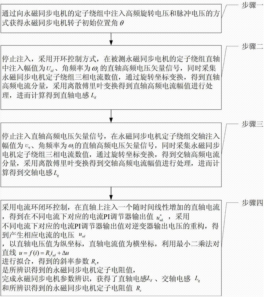
[0035] Specific implementation mode 1. Combination Figure 1 to Figure 5 Describe this embodiment, the parameter off-line identification method under the static state of permanent magnet synchronous motor described in this embodiment comprises the following steps:

[0036] Step 1. Obtain the rotor initial position angle θ of the permanent magnet synchronous motor by injecting high-frequency rotating voltage and pulse voltage into the stator winding of the permanent magnet synchronous motor;

[0037] Step 2: Stop injecting voltage, adopt open-loop control mode, and inject amplitude U into the direct axis of the stator winding of the permanent magnet synchronous motor under test id , the angular frequency is ω i Direct-axis sinusoidal high-frequency voltage vector signal;

[0038] At the same time, the three-phase current value of the stator winding of the permanent magnet synchronous motor is collected, and the direct-axis high-frequency current component is obtained through ...

specific Embodiment approach 2

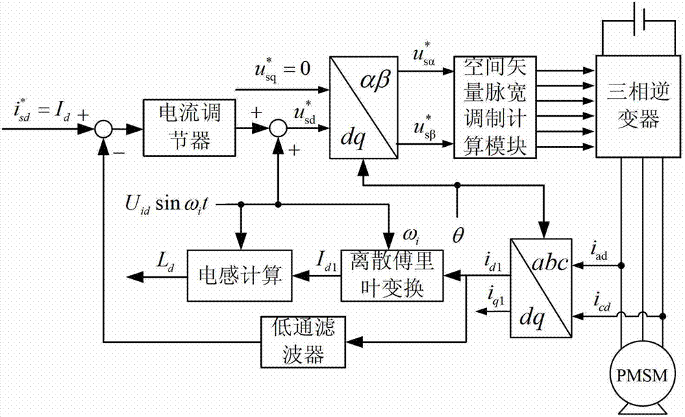
[0048] Embodiment 2. The difference between this embodiment and the parameter offline identification method of the permanent magnet synchronous motor in the static state described in Embodiment 1 is that the discrete Fourier transform pair described in step 2 is used to obtain the direct-axis high-frequency current amplitude. The value is processed, and then calculated to obtain the direct axis inductance L d The specific process is:

[0049] Step 21. Generate the amplitude U through the look-up table method id , the angular frequency is ω i The direct-axis sinusoidal high-frequency voltage vector signal U id sin ω i t,

[0050] Step 22. Calculate the current of the B-phase winding by collecting the obtained current of the A-phase winding and the current of the C-phase winding,

[0051] Step two and three, using the transformation formula from the three-phase stationary coordinates to the two-phase rotating coordinate system, to obtain the direct-axis current value and th...

specific Embodiment approach 3

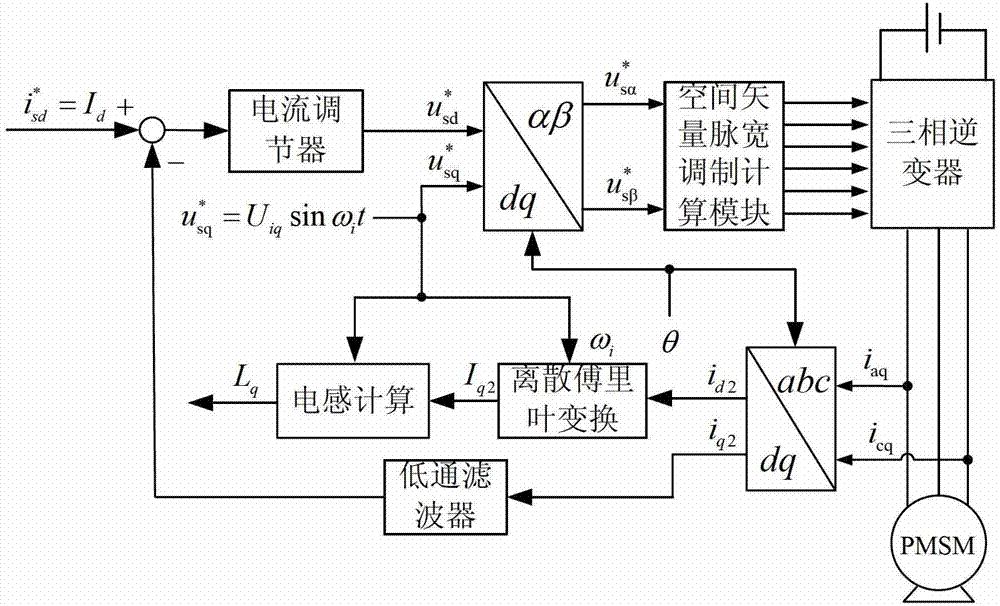
[0054] Specific Embodiment 3. The difference between this embodiment and the parameter offline identification method of the permanent magnet synchronous motor in the static state described in the specific embodiment 1 is that the quadrature-axis high-frequency current amplitude is obtained by using the discrete Fourier transform described in step 3. , and then calculate the quadrature axis inductance L q The specific process is:

[0055] Step 31. Generate an amplitude value of U through the look-up table method iq , the angular frequency is ω i The direct-axis sinusoidal high-frequency voltage vector signal U iq sin ω i t,

[0056] Step 32: Calculate the current of the B-phase winding by collecting the obtained current of the A-phase winding and the current of the C-phase winding,

[0057] Step 33, using the transformation formula from the three-phase stationary coordinates to the two-phase rotating coordinate system to obtain the direct axis current value and the quadrat...


PUM


Abstract

The invention discloses a parameter offline identification method for a permanent magnet synchronous motor under the condition of rest, belonging to the field of motor control and solving the problems of rotor external locking, overlong identification time, poor result consistency, poor practicability and the like of the existing parameter offline identification method for the permanent magnet synchronous motor under the condition of rest. The parameter offline identification method comprises the steps of: always keeping a rotor in a rest state, injecting a high-frequency voltage signal in a straight axis of a rotor winding, detecting a three-phase stator current and transforming into two-phase rotational coordinates, carrying out discrete Fourier transform on the current to obtain a straight axis high-frequency current amplitude so as to obtain a straight-axis inductance value through calculation; then injecting a high-frequency voltage signal in a quadrature axis of the stator winding, obtaining a quadrature axis inductance value by using the same method; and then introducing a linearly increasing current into the straight axis of the stator winding so as to obtain a voltage generating a corresponding current through reconstruction of a voltage of an inverter, calculating and fitting a straight slope by using a least square method by using a straight axis voltage value as a longitudinal coordinate and a straight axis current value as a transverse coordinate, and finally obtaining a slope value, wherein the slope value is a stator resistance value.

Description

technical field [0001] The invention relates to the field of motor control, in particular to a parameter off-line identification method in a static state of a permanent magnet synchronous motor. Background technique [0002] In recent years, the permanent magnet synchronous motor speed control system has gradually become a research hotspot in the field of AC speed control transmission, and has been widely used in aerospace, electric vehicles and other fields. This is due to the advantages of permanent magnet synchronous motors compared with traditional induction motors: high efficiency and energy saving, high power factor, high power density, strong overload capacity, etc. Permanent magnet synchronous motors have become an ideal choice for frequency conversion and speed regulation electric drive systems . [0003] At present, many control technologies of permanent magnet synchronous motor speed control systems, such as maximum torque current ratio control, field weakening c...

Claims


Application Information

Patent Timeline
Patent Type & Authority Applications(China)
IPC IPC(8): H02P21/14H02P21/22
Inventor 王高林詹瀚林李卓敏张国强贵献国徐殿国
Owner HARBIN INST OF TECH
Why Eureka
Try Eureka