Check patentability & draft patents in minutes with Patsnap Eureka AI!

Regeneration method of coal liquefied oil hydrogenation deactivated catalyst

A technology for deactivating catalysts and coal liquefied oil, applied in catalyst regeneration/reactivation, physical/chemical process catalysts, chemical instruments and methods, etc., can solve the problems of large loss of catalyst activity, reduction of catalyst cost, deterioration of catalyst properties, etc. Achieve the effect of high equipment and operating costs, reducing costs, and reducing production and operating costs

Active Publication Date: 2013-07-03
CHNA ENERGY INVESTMENT CORP LTD +2
View PDF2 Cites 17 Cited by
  • Summary
  • Abstract
  • Description
  • Claims
  • Application Information

AI Technical Summary

Problems solved by technology

[0008] For this reason, the present invention provides a kind of regeneration method aimed at the deactivated catalyst of coal liquefied oil hydrogenation, this method can effectively eliminate the catalyst deactivation caused by the heat generated by the combustion of a large amount of C and S on the deactivated catalyst, and overcome the regeneration Afterwards, the nature of the catalyst deteriorates, the highly dispersed active metals condense, and the catalyst loses a lot of activity. At the same time, it can reduce the investment in equipment and effectively reduce the cost of catalyst regeneration.

Method used


Image

  • Regeneration method of coal liquefied oil hydrogenation deactivated catalyst
  • Regeneration method of coal liquefied oil hydrogenation deactivated catalyst
  • Regeneration method of coal liquefied oil hydrogenation deactivated catalyst

Examples


Embodiment 1

[0077] The regeneration steps and parameters of regeneration catalyst A are as follows:

[0078] a0. In the stage of heating nitrogen with oil, the hydrogenation deactivated catalyst discharged from the T-Star fluidized bed is collected online, and the oil content on the surface of the catalyst is removed by means of heating nitrogen with oil, so that it can reach the conditions for regeneration. The process parameters of the hot nitrogen belt oil are: temperature 250-280°C, gas agent ratio of the hot nitrogen belt oil 300-400 / h (vol / vol), and reaction time 3-5 hours.

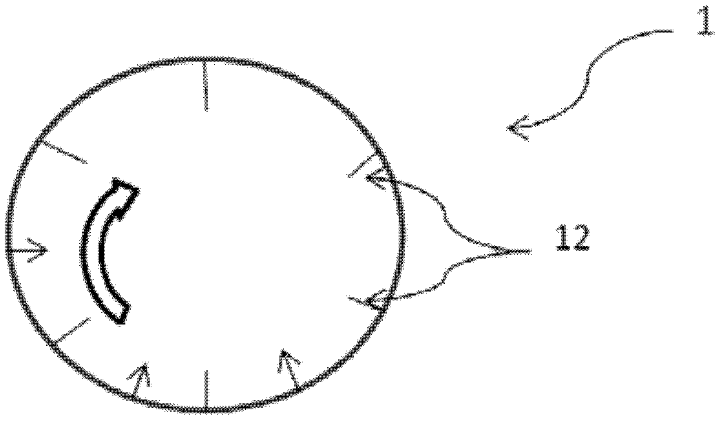
[0079] a. In the catalyst loading stage, according to the volume of the isothermal zone in the rotary kiln, the inactivated catalyst after deoiling is sieved and sent into the rotary kiln, and the deactivated catalyst is spread in the rotary kiln isothermal by the slow rotation of the rotary kiln. On the inner surface of the zone, the thickness of the catalyst is generally controlled at a thickness of 0.5-1.0cm...

Embodiment 2

[0098] The regeneration procedure of the regenerated catalyst B is consistent with that of the regenerated catalyst A, and the regeneration parameters are shown in Table 3. The activity of regenerated catalyst B under the same hydrogenation process parameters of coal liquefaction raw oil and direct coal liquefaction oil is shown in Table 7.

[0099] Table 3 Coking parameters of regenerated catalyst B

[0100]

Embodiment 3

[0102] The regeneration steps of the regenerated catalyst C are consistent with those of the regenerated catalyst A, and the regeneration parameters are shown in Table 4. The activity of regenerated catalyst C under the same hydrogenation process parameters of coal liquefaction feed oil and direct coal liquefaction oil is shown in Table 7.

[0103] Table 4 Coking parameters of regenerated catalyst C

[0104] Regeneration Phase Parameters


PUM


Abstract

The invention provides a regeneration method of a coal liquefied oil hydrogenation deactivated catalyst, which comprises: (a) a catalyst filling phase in which the hydrogenation catalyst to be regenerated is filled into a rotary kiln regeneration device (1); (b) a low temperature scorching phase in which heated process air with a low oxygen content is injected at a temperature of 200 DEG C-350 DEG C, wherein the oxygen content of the process air is 1-10 vol%, and the gas-agent ratio during the catalyst regeneration reaction is 2000-5000 / h (vol / vol); (c) a transition phase in which the regeneration temperature of the catalyst is firstly increased after the temperature increase of a bed layer in the low temperature scorching phase is not more than 5 DEG C and the content of CO2 and SO2 in the air is less than 0.05 wt%, then the oxygen concentration of the process air is increased; (d) a high temperature scorching phase in which high temperature scorching of the catalyst is carried out at 450 DEG C-470 DEG C when the temperature increase of the bed layer in the transition phase is within 5 DEG C and the content of CO2 and SO2 in the air is less than 0.05 wt%; (e) a purification phase. The method can effectively prevent catalyst deactivation due to heat generated during combustion of a lot of C and S in the deactivated catalyst, reduce equipment investment, and reduce catalyst regeneration cost.

Description

technical field [0001] The invention generally relates to a deactivated catalyst regeneration method for a hydrogenation catalyst, in particular to a method for regenerating a deactivated catalyst for hydrogenation of coal liquefied oil. Background technique [0002] Due to the structural characteristics of hydrocarbons in coal raw materials, the density of oil produced by coal liquefaction is as high as 0.9500g / cm 3 Above, the nitrogen content is as high as 0.28wt%. At the same time, coal liquefied oil contains more colloids, olefins, carbon residues, and polycyclic aromatic hydrocarbons. These coking precursors (or coking precursors) are extremely easy to dehydrogenate, carbonize, and coke at high temperatures. , causing a decrease in catalyst activity, which in turn causes blockage of the reactor bed, resulting in an increase in the pressure drop of the reactor bed. [0003] In view of the above characteristics of coal liquefied oil, the domestic coal liquefied oil hydro...

Claims


Application Information

Patent Timeline
IPC IPC(8): B01J38/20
Inventor 马辉石玉林吴秀章胡云剑金环年
Owner CHNA ENERGY INVESTMENT CORP LTD
Features
  • R&D
  • Intellectual Property
  • Life Sciences
  • Materials
  • Tech Scout
  • Unparalleled Data Quality
  • Higher Quality Content
  • 60% Fewer Hallucinations
Learn More