Submersed nozzle for slab continuous casting

A slab continuous casting and immersion technology, which is applied to casting equipment, casting melt containers, manufacturing tools, etc., can solve the problems of increasing investment in continuous casting crystallizers, high use costs, waste of energy, etc., and is suitable for Low cost of large-scale industrial production, transformation and use, and the effect of widely popularizing and applying value

Inactive Publication Date: 2013-07-10
BAOSHAN IRON & STEEL CO LTD
View PDF4 Cites 3 Cited by
  • Summary
  • Abstract
  • Description
  • Claims
  • Application Information

AI Technical Summary

Problems solved by technology

However, these designs are difficult to fundamentally improve the flow field in the crystallizer
Existing nozzles such as figure 1 , 2 As shown, the spit holes 3 are mostly arranged on both sides of the bottom of the nozzle body 2, and a pair of spit holes 3 are symmetrically arranged at the center line of the two side walls. The flow field in the crystallizer 4 during casting is as follows: image 3 As shown, in the area near the center line in the mold 4, two molten steels flowing in opposite directions collide and become a flow dead zone 1, so the steel flow cannot produce a flow field with a stirring effect in the mold 4
With the development of continuous casting technology, especially electromagnetic metallurgy technology, such as Figure 4 As shown, in the crystallizer 4, the electromagnetic stirring device 5 is used to promote the stirring of the steel stream, which can reduce subcutaneous inclusions and air bubbles, and has been proved in large-scale industrial production. However, for continuous casting machines without electromagnetic stirring equipment Generally speaking, it is very difficult to achieve this effect or it is necessary to increase a large investment to transform the continuous casting mold, which is very costly, and the power utilization efficiency of the electromagnetic stirring equipment is very low, the use cost is also high, and wasted a lot of energy
[0003] A nozzle that can produce a stirring effect similar to an electromagnetic field, such as patent 99101507.X, discloses an "X"-shaped submerged nozzle that can make the molten steel in the crystallizer rotate by itself, by setting two circular arc plates arranged in an X shape in the nozzle , so that the outflowing molten steel generates a vortex, which plays a role in stirring the molten steel in the crystallizer; but the deflector added inside the nozzle is not only difficult to manufacture, but also relies on the downward spit hole to generate the steel flow rotation, which is affected by the molten steel The effect of flow velocity is only effective near the water outlet, and it has no effect at places far away from the water outlet
Therefore, it cannot be disturbed for large-volume casting such as slabs. Obviously, it cannot be implemented in large-scale industrial production and is not feasible.
Moreover, in order to generate a vortex-type molten steel flow, the spit hole is downward, and there is no side exit hole for the slab, which will lead to low temperature of the molten steel on the meniscus of the crystallizer, serious heat shortage, poor melting of mold slag, and steel breakout Accidents or serious surface defects; the addition of deflectors inside the nozzle increases the flow resistance of molten steel, and this nozzle will soon be blocked by the adhesion and accumulation of inclusions on the deflector, resulting in the termination of casting; once The guide plate is not fixed firmly and falls off, it will enter the molten steel and cannot float up, and it will become a large inclusion, which is extremely harmful to the product

Method used


Image

  • Submersed nozzle for slab continuous casting
  • Submersed nozzle for slab continuous casting
  • Submersed nozzle for slab continuous casting

Examples


Embodiment 1

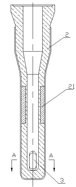
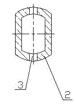
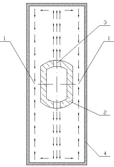
[0019] like Figure 5 , 6 As shown, a submerged nozzle for slab continuous casting, the middle part of the nozzle body 2 is the slag line area 21, the upper half of the nozzle body 2 is circular, in order to be well connected with the sliding nozzle of the tundish, the lower The half part gradually transitions into a flat shape. The material of the nozzle body 2 is aluminum carbon. The molten steel is cast from the tundish into the crystallizer through the submerged nozzle, which plays the role of isolating the steel flow from the air and preventing the secondary oxidation of the molten steel. The purity of molten steel can be improved; a pair of spit holes 3 are provided on both sides of the bottom of the nozzle body 2, and the pair of spit holes 3 are arranged eccentrically. 3 is close to the inner wall of one side of the bottom of the nozzle body 2, and the other side of the spit hole 3 is close to the diagonal line of the bottom of the nozzle body 2; Figure 7 As shown, ...


PUM


Abstract

The invention relates to the field of molten steel continuous casting, in particular to a submersed nozzle for slab continuous casting. A pair of discharge holes (3) are eccentrically formed in the two sides of a central line at the bottom of a nozzle body respectively; one discharge hole is close to the inner wall on one side at the bottom of the nozzle body; and the other discharge hole is close to the inner wall on the other side of a diagonal line at the bottom of the nozzle body. According to the submersed nozzle, the pair of eccentric discharge holes can form a mixing flow field in a crystallizer in the casting process, so that a good effect of reducing subsurface inclusions and air bubbles can be obtained, a flowing dead zone is removed at the same time, the molten steel temperature is uniform, and casting powder is conveniently molten and uniformly flows into the crystallizer, thereby improving the slab surface quality; and compared with electromagnetic mixing equipment, the investment cost can be greatly reduced, the slab continuous casting operation is also easily carried out on the conventional casting machine at the same time, the crystallizer of the continuous casting machine does not need to be complicatedly improved, the improvement and usage costs are very low, the energy is saved, the environment is protected, and the value in popularization and application is wide.

Description

technical field [0001] The invention relates to the field of continuous casting of molten steel, in particular to a submerged nozzle for slab continuous casting. Background technique [0002] At present, continuous casting of molten steel is a technology in which the molten steel in the ladle is transferred through the tundish, and then poured into the crystallizer for cooling and continuous solidification into a billet shell. In order to prevent the oxidation of molten steel in the continuous casting process, fully enclosed pouring is required, and the submerged nozzle needs to be used for protection during the process from the tundish to the crystallizer. The submerged nozzle is a key functional refractory material for continuous casting. Its quality and design are directly related to the continuous casting process and product quality. The current nozzle design improvements are all based on reducing clogging or reducing the impact strength of steel flow. For example, the ...

Claims


Application Information

Patent Timeline
Patent Type & Authority Applications(China)
IPC IPC(8): B22D11/10B22D41/50
Inventor 职建军王洪亮于燕文刘国强
Owner BAOSHAN IRON & STEEL CO LTD
Why Eureka
Try Eureka