

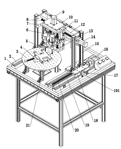
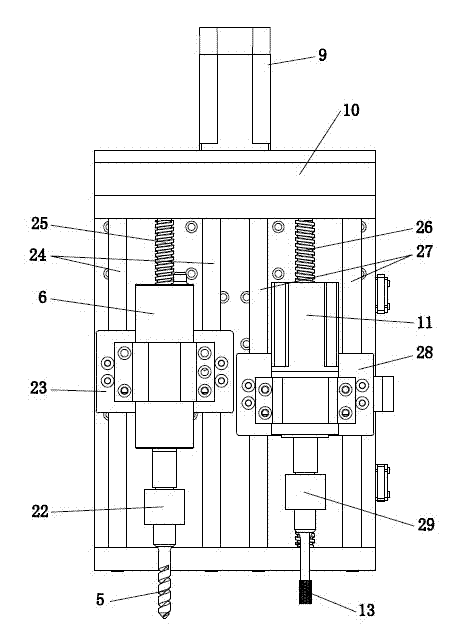
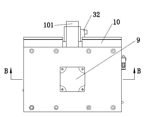
Numerical control drilling and tapping all-in-one machine and control method thereof
An integrated tapping and screw technology, used in other manufacturing equipment/tools, manufacturing tools, metal processing machinery parts, etc., can solve the problems of low processing efficiency, high manufacturing machinery cost, waste of manpower, etc., and achieve good processing accuracy. , High degree of automation, good control and adjustment effect
- Summary
- Abstract
- Description
- Claims
- Application Information
AI Technical Summary
Problems solved by technology
Method used
Image

Examples
Embodiment Construction
[0039] Embodiments of the present invention are described in detail below, examples of which are shown in the drawings, in which the same or similar reference numerals denote the same or similar elements or elements having the same or similar functions. The embodiments described below by referring to the figures are exemplary only for explaining the present invention and should not be construed as limiting the present invention.
[0040] In the description of the present invention, the orientations or positional relationships indicated by the terms "Y-direction", "X-direction", "Z-direction", "upper" and "lower" are based on the orientation or positional relationships shown in the accompanying drawings, and are only No limitation on the invention is to be construed for the convenience of describing the invention without requiring that the invention must be constructed and operated in a particular orientation.
[0041] Such as Figures 1 to 8As shown, it is a CNC drilling and ...
PUM
 Abstract
Description
Claims
Application Information