
a vacuum pump

A vacuum pump and pump body technology, applied in pumps, machines/engines, mechanical equipment, etc., can solve problems affecting the vacuum degree of the system, oil and gas pollution, debris falling into the cavity of the pump body, and increased bearing load, etc., to achieve light weight , Save oil, reduce friction

Active Publication Date: 2015-12-30
ZHEJIANG VACUUM EQUIP GROUP
View PDF6 Cites 0 Cited by
  • Summary
  • Abstract
  • Description
  • Claims
  • Application Information

AI Technical Summary

Problems solved by technology

However, it can be seen from the structure that the exhaust port is set on the top of the pump body and opened upward, and an exhaust valve is installed in the exhaust port. During long-term use, the valve plate of the exhaust valve will be damaged after wear and corrosion. The generated debris is extremely easy to fall into the cavity of the pump body, which will directly damage the entire vacuum pump
Furthermore, due to gravity, the lower surface of the sliding rod of the spool valve is close to the surface of the connecting piece, so that there are many gaps above and no gap below, and the oil and gas pressure generated during the operation of the spool valve leads to the gap between the connecting piece, the spool valve rod and the small cylinder. Insufficient lubrication, the upper part causes oil and gas to flow back to the air inlet due to the large gap, which affects the vacuum degree of the system and oil and gas pollution
And the superposition of exhaust pressure and gravity increases the load on the bearing

Method used


Image

  • a vacuum pump
  • a vacuum pump
  • a vacuum pump

Examples


Embodiment Construction

[0025] The following are specific embodiments of the present invention and in conjunction with the accompanying drawings, the technical solutions of the present invention are further described, but the present invention is not limited to these embodiments.

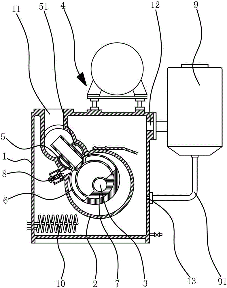
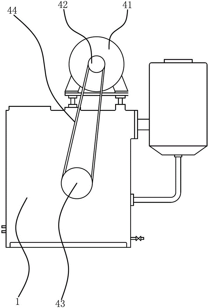
[0026] Such as figure 1As shown, a vacuum pump includes a pump body 1 and a pump shaft 3. The pump body 1 has an inlet 11 and an outlet 12. The inlet 11 is set on the top of the pump body 1, and the outlet 12 is set on the side wall of the pump body 1. The pump shaft 3 is set in the pump body 1. There is a chamber inside the pump body 1, and the chamber is filled with oil, which plays a role of lubrication and sealing. At the same time, when the discharged gas is less, the oil can help the gas to push the exhaust valve 8 together. The pump body 1 is provided with a cylinder body 2. The cylinder body is composed of a large cylinder and a small cylinder connected with the large cylinder. The inlet 11 is connected with the s...


PUM


Abstract

The invention provides a vacuum pump, belongs to the technical field of machinery, and solves the problem that the whole vacuum pump is damaged as fragments generated when an exhaust valve of the conventional vacuum pump is damaged because of abrasion and corrosion are likely to fall into the chamber of the pump body. The vacuum pump comprises a pump body and a pump shaft, wherein a cylinder is arranged inside the pump body; the cylinder comprises a large cylinder and a small cylinder; a connecting piece is arranged inside the small cylinder; a sliding valve is arranged inside the large cylinder; the sliding valve comprises a valve body and an eccentric pulley; one end of a pump shaft is connected with the eccentric pulley; a sliding rod is arranged on the valve body; the sliding rod is connected with the connecting piece in a sliding manner; the other end of the pump shaft is connected with a power mechanism; an exhaust valve is fixed at the part where the large cylinder is connected with the small cylinder; and an outlet of the exhaust valve faces downwards. The vacuum pump has the advantages that the vibration of the vacuum pump is reduced, the friction is reduced, the possibilities of oil return and air leakage are reduced, the energy consumption is reduced, and the service life of the vacuum pump is prolonged.

Description

technical field [0001] The invention belongs to the technical field of machinery, and relates to a vacuum device, in particular to a vacuum pump. Background technique [0002] Vacuum pump is a kind of equipment that can continuously inhale and discharge gas to achieve the purpose of pumping. It is widely used in metallurgy, petroleum, chemical industry, medicine, food, electronic appliances, space simulation and high-end physics and other industries. There are many kinds of vacuum pumps, including molecular pumps, diffusion pumps, Roots pumps, dry pumps, reciprocating vacuum pumps, rotary vane vacuum pumps, water ring vacuum pumps, slide valve vacuum pumps, etc. Among them, slide valve vacuum pumps are the same as rotary vane vacuum pumps. Positive displacement vacuum pump is suitable for vacuum smelting, vacuum drying, vacuum distillation, vacuum evaporation, vacuum concentration, vacuum crystallization, vacuum welding, vacuum coating, vacuum impregnation, vacuum simulation...

Claims


Application Information

Patent Timeline
Patent Type & Authority Patents(China)
IPC IPC(8): F04C25/02
Inventor 许涛罗根松
Owner ZHEJIANG VACUUM EQUIP GROUP
Learn More