Rotor position detection method of brushless direct current motor without sensor

A brushless DC motor and rotor position detection technology, applied in the direction of electronic commutator, etc., can solve the problems of low withstand voltage, no speed of motor, motor vibration, etc.

Inactive Publication Date: 2013-07-10
JIANGSU XIECHANG ELECTRONICS TECH
View PDF5 Cites 11 Cited by
  • Summary
  • Abstract
  • Description
  • Claims
  • Application Information

AI Technical Summary

Problems solved by technology

Because the installation of Hall is cumbersome, and 80% of the faults of brushless motors are caused by Hall elements, and even a considerable part of the fault misjudgment of brushless motor controllers is also caused by Hall elements.
The performance and life of the Hall element will be affected by electromagnetic interference in the circuit, thus affecting the normal operation of the entire circuit system
Due to its low withstand voltage value, it is very easy to cause breakdown when the motor coil leaks
At the same time, the installation accuracy of the Hall element directly affects the operation performance of the motor of the brushless electric vehicle. If there is a problem, it is necessary to replace the Hall, and generally three of them are required to ensure the consistency of the Hall and make the brushless motor work normally. Even if some motor manufacturers use high-end Hall elements, the Hall elements will eventually become the bottleneck of the motor under the ever-increasing demand for motor power
In recent years, although Hall-free electric vehicle controllers have also appeared on the market, based on the previous scheme, there is no Hall controller. When the motor speed is close to the zero speed area, the exact position of the current rotor cannot be known. Vibration will cause discomfort when riding and starting, and may even fail to start on roads with a certain slope in some areas or under heavy load
In the final analysis, the current Hall-free controllers need to judge the current coil position. There are also some Hall-less controllers on the market, which use the motor to rotate to detect the back EMF. It brings about various problems such as motor jitter, failure to start, poor start, etc.

Method used


Image

  • Rotor position detection method of brushless direct current motor without sensor
  • Rotor position detection method of brushless direct current motor without sensor
  • Rotor position detection method of brushless direct current motor without sensor

Examples


Embodiment Construction

[0017] The present invention will be described in further detail below through specific examples.

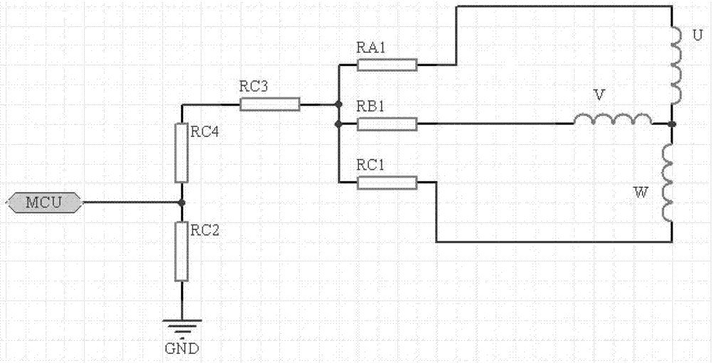
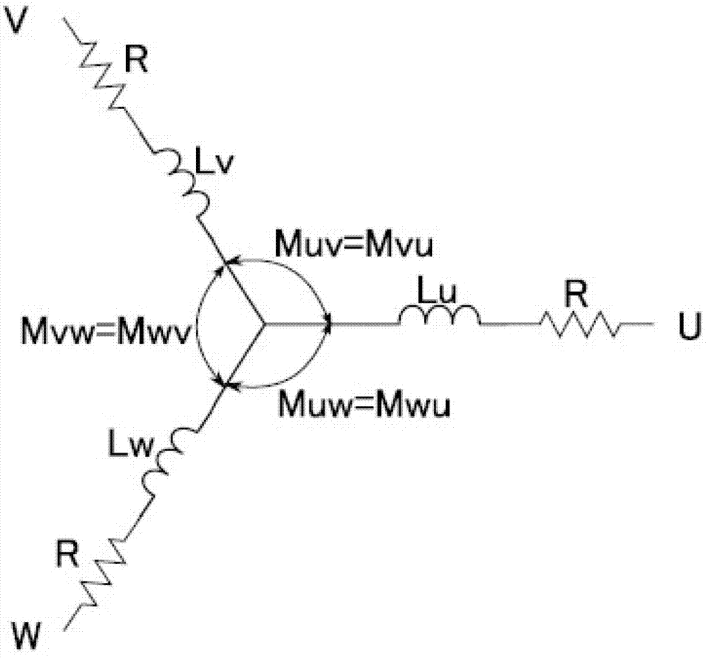
[0018] A method for detecting the rotor position of a sensorless DC brushless motor, the detection method includes a detection method for the starting position of the rotor and a detection method for the rotor position after the motor rotates, wherein the detection method for the starting position of the rotor adopts the motor coil magnetic flux with the permanent magnet The current relative position of the coil magnetic field and the permanent magnetic field is judged by the law of the magnetic field change, specifically: the three-phase circuit v, u, w of the motor are respectively connected to the symmetrical voltage Uvu, Uuv with the same pulse width and the same voltage value in advance. , Uvw, Uwv, Uuw, Uwu, the voltage is not enough to deflect the rotor of the motor, the voltage or current of the three-phase brushless DC motor coil is sampled, and the rotor coil and the pe...


PUM


Abstract

The invention discloses a rotor position detection method of a brushless direct current motor without a sensor. The rotor position detection method of the brushless direct current motor without the sensor comprises a detection method of a rotor start position and a detection method of a rotor position after the motor rotates. According to the detection method of the rotor start position, current relative positions of a coil magnetic field and a permanent magnetic field can be judged according to a law of variation of motor coil magnetic flux along with the permanent magnetic field, specially, symmetric voltage Uvu and Uuv, Uvw and Uwv, and Uuw and Uwu with equal pulse width and the same voltage value are connected with three phase circuits v, u and w of the motor in pairs, the voltage can not enable a rotor of the motor to deflect, the voltage or current of brushless direct current motor coil three phases is sampled, and current relative positions of coil of the rotor and the permanent magnetic field when the motor is started can be estimated according to a voltage circuit equation. According to the rotor position detection method of the brushless direct current motor without the sensor, the position of the rotor can be detected without the requirement for motor rotation, and therefore a current blind starting mode of the brushless direct current motor without a Hall sensor is replaced.

Description

technical field [0001] The invention relates to a method for detecting the rotor position of a DC brushless motor, in particular to a method for detecting the rotor position of a sensorless DC brushless motor. Background technique [0002] Nowadays, with the promotion and popularization of brushless motors, the inherent problems also appear at the same time, which also makes the majority of users feel a little headache. Because the Hall installation is cumbersome, and 80% of the faults of the brushless motor are caused by the Hall element, and even a considerable part of the fault misjudgment of the brushless motor controller is also caused by the Hall element. The performance and life of the Hall element will be affected by electromagnetic interference in the circuit, thus affecting the normal operation of the entire circuit system. Due to its low withstand voltage value, it is very easy to cause breakdown when the motor coil leaks electricity. At the same time, the insta...

Claims


Application Information

Patent Timeline
Patent Type & Authority Applications(China)
IPC IPC(8): H02P6/18
Inventor 顾挺葛小峰
Owner JIANGSU XIECHANG ELECTRONICS TECH
Why Eureka
Try Eureka