
Calibration of a probe in ptychography

A detection area and detector technology, applied in measuring devices, radiation measurement, X/γ/cosmic radiation measurement, etc., can solve problems such as algorithm failure to generate images, inaccurate sample estimation, algorithm divergence, etc.

Active Publication Date: 2013-07-10
PHASE FOCUS
View PDF5 Cites 26 Cited by
  • Summary
  • Abstract
  • Description
  • Claims
  • Application Information

AI Technical Summary

Problems solved by technology

However, it is possible that the algorithm failed to produce an accurate image
In some cases, each iteration of ePIE will produce less accurate estimates of specimen and detection than those produced by previous iterations, and the algorithm is said to diverge

Method used


Image

  • Calibration of a probe in ptychography
  • Calibration of a probe in ptychography
  • Calibration of a probe in ptychography

Examples


Embodiment Construction

[0030] Like reference numerals refer to like parts in the figures.

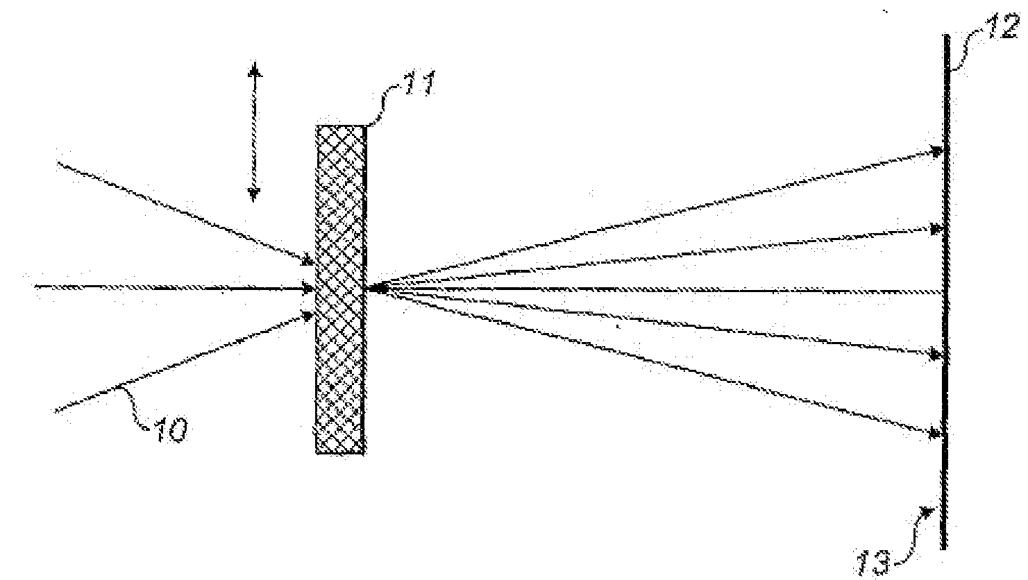
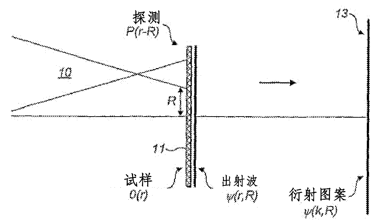
[0031] figure 1 It is shown how to develop the scatter pattern and how to use the scatter pattern to determine image data corresponding to the information of the structure of the target object. It will be understood that the term target object refers to any sample or object placed in the path of incident radiation causing scattering of that radiation. It will be appreciated that the target object should be at least partially transparent to incident radiation. The target object may or may not have some repetitive structure. Alternatively, the target object may be fully or partially reflective, in which case the scattering pattern is measured based on the reflected radiation.

[0032] Incident radiation 10 is caused to fall on a target object 11 . It will be understood that the term radiation should be interpreted broadly as energy from a radiation source. This would include: electromagnetic radiation incl...


PUM


Abstract

A method of providing image data for constructing an image of a region of a target object, comprising providing a reference diffraction pattern of a reference target object; determining an initial guess for a probe function based upon the reference diffraction pattern; and determining, by an iterative process based on the initial guess for the probe function and an initial guess for an object function, image data for a target object responsive to an intensity of radiation detected by at least one detector.

Description

technical field [0001] The invention relates to a method and a device for providing image data of the type which can be used to construct an image of a region of a target object. In particular, but not exclusively, the invention relates to methods of providing such image data using an iterative process using an unknown detection function. Background technique [0002] Many types of imaging techniques are known for deriving spatial information of an object of interest (sometimes referred to as a specimen). However, direct imaging of target specimens by conventional means such as bright field microscopy is often not possible. For example, in traditional transmission imaging, objects are illuminated by plane wave illumination. The waves scattered by the object interfere again through the lens to form an image. In the case of very short wavelength imaging (X-ray or electron), this technique has a number of known difficulties related to lens-induced aberrations and instabiliti...

Claims


Application Information

Patent Timeline
Patent Type & Authority Applications(China)
IPC IPC(8): G01T1/29
CPCG01N23/205G01T1/2914G01N23/20G06V10/255G06F18/213
Inventor 安德鲁·迈登
Owner PHASE FOCUS
Learn More