Wind power generation apparatus

A technology for wind power generation devices and generators, which is applied to wind turbine components, wind energy power generation, wind turbines, etc., can solve the problem that it is difficult to reduce torque fluctuations, and achieve the effect of reducing mechanical loads.

Inactive Publication Date: 2013-07-17
SUMITOMO HEAVY IND LTD
9 Cites 3 Cited by

AI-Extracted Technical Summary

Problems solved by technology

[0006] However, the pitch control has a limit on the speed at which the wind turbine blades can be moved, and it is difficult to alleviate torque fluctuations caused by the wind turbin...

Method used

[0084] Furthermore, in the wind power generator 1 according to this embodiment, the first driver 104 and the second driver 108 are controlled based on the wind speed measured by the anemometer installed around the wind power generator 1. Therefore, the driver can be controlled more accurately.
[0091] FIG. 9 is a graph showing the relationship between the natu...

Abstract

The invention provides a wind power generation apparatus which can reduce mechanical loads of key components caused by variation of torque generated by windmill blades blown by wind. According to the wind power generation, a generator (20) converts the torque generated by windmill blades (5) blown by wind. The wind power generation apparatus has a power transmission system which transmits power to the generator (20) from the windmill blades (5), a first alleviation mechanism which alleviates torque variation generated by wind shear in the torque variation applied to the power transmission system, and a second alleviation mechanism which alleviates torque variation caused by non-wind shear in the torque variation applied to the power transmission system.

Application Domain

Wind motor controlMachines/engines +3

Technology Topic

Wind forceElectric generator +9

Image

  • Wind power generation apparatus
  • Wind power generation apparatus
  • Wind power generation apparatus

Examples

  • Experimental program(2)

Example

[0034] (first embodiment)
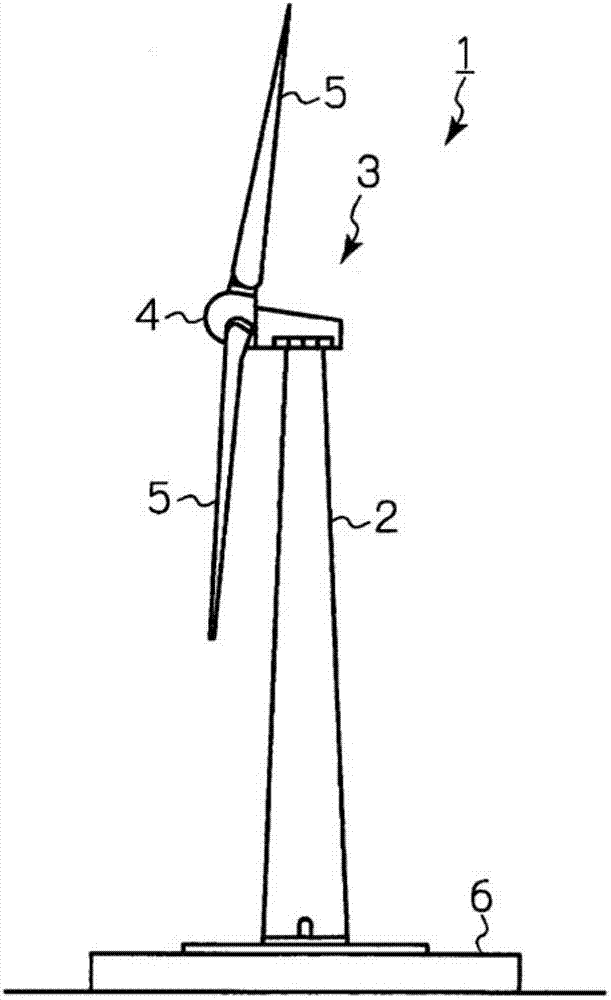
[0035] figure 1 It is a side view of the wind turbine generator 1 which concerns on 1st Embodiment. The wind turbine generator 1 includes a strut 2 erected on a base 6 , a nacelle 3 provided on an upper end of the strut 2 , and a rotor head 4 rotatably assembled with respect to the nacelle 3 . A plurality of (eg, three) windmill blades (also referred to as windmill blades) 5 are mounted on the rotor head 4 . The wind turbine generator 1 is a so-called constant-speed operation windmill, and after the rotational speed of the wind turbine blades 5 reaches a predetermined rated rotational speed, the wind turbine blades 5 rotate at the rated rotational speed.
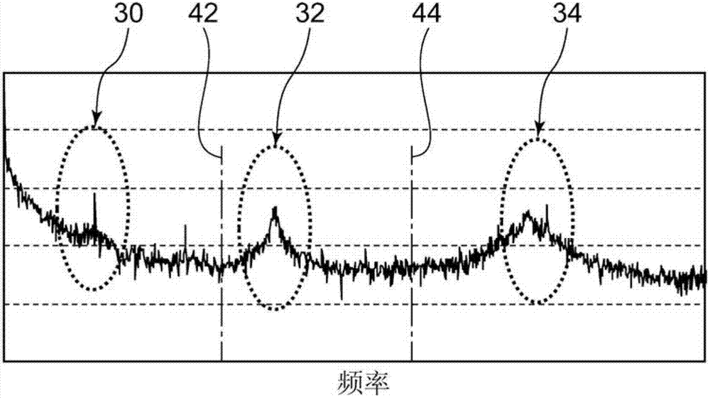
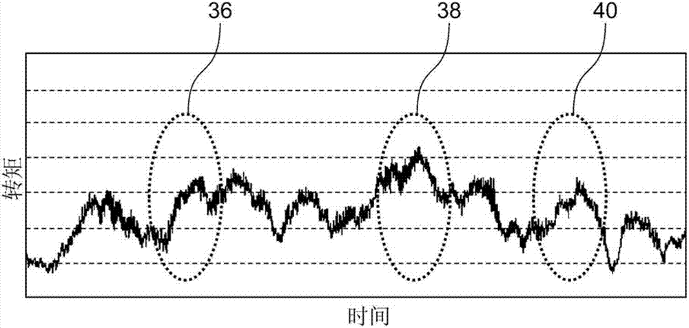
[0036] FIGS. 2( a ) and ( b ) are diagrams showing fluctuations in torque generated when the wind turbine blade 5 receives wind. Figure 2(a) is the frequency spectrum of torque, and Figure 2(b) is the time series data of torque. By analyzing the torque data represented by FIGS. 2( a ) and ( b ), the inventors have come to the conclusion that there are roughly two types of torque fluctuations to be reduced.
[0037] (1) Torque fluctuation due to rotation of wind turbine blade 5
[0038] This torque fluctuation is mostly stable, that is, the frequency is substantially constant. For example, in the frequency spectrum of FIG. 2( a ), peaks are seen in the first-order component 30 , the third-order component 32 , and the sixth-order component 34 corresponding to the rated rotational speed of the wind turbine blade 5 . The primary component 30 has the rated rotational speed as the approximate center. The tertiary component 32 has the approximate center of the product of the rated rotational speed and the number of sheets (=3), and the sixth-order component 34 has the approximate center of twice the product of the rated rotational speed and the number of sheets (=3). In addition, it is understood that the fact that the peak is not seen in the second-order component or the fourth-order component is because the wind turbine blade 5 is approximately three-fold symmetrical (that is, it overlaps itself when rotated by 120 degrees).
[0039] The inventors found the following relationship between the rotational speed of the wind turbine blade 5 and the torque fluctuation. When the rotational speed of the wind turbine blade 5 is N, the number of wind turbine blades is n, and P is a natural number, peaks tend to appear at N and nNP in the torque spectrum. This peak is due to wind shear. That is, the torque fluctuates due to the uneven wind speed on the wind receiving surface of the wind turbine generator 1, and the torque fluctuation appears as a peak at N and nNP.
[0040] If the torque fluctuation overlaps with the system natural frequency, resonance may occur and the mechanical load on the components of the wind turbine generator 1 may be further increased.
[0041] (2) Sudden torque fluctuations caused by gusts, etc.
[0042] For example, in the time series data of Fig. 2(b), in addition to the minute torque fluctuations corresponding to the first-order component 30, the third-order component 32, or the sixth-order component 34 described above, a longer time span ( TimeSpan) torque fluctuation. In particular, in the portions 36 , 38 , and 40 surrounded by dotted lines in FIG. 2( b ), the torque increases during the rise time from about 10 seconds to about 20 seconds.
[0043] In the wind turbine generator 1 according to the present embodiment, the following three approaches are adopted in order to effectively reduce the mechanical load on the components of the speed increaser caused by the above-mentioned two kinds of torque fluctuations.
[0044] (A) The driver is introduced into the torque arm supporting the speed increaser, and the driver is actively controlled according to the torque. According to this approach, the mechanical load caused by sudden torque fluctuation mainly caused by wind gusts and the like can be reduced.
[0045](B) Two types of torque fluctuation mitigation mechanisms are introduced: for stable fluctuations and for sudden fluctuations. According to this approach, based on the knowledge of the present inventors that the fluctuation of the torque to be reduced has the above-mentioned two types, the torque fluctuation reduction control can be performed more accurately. It is a concept to carry out the necessary control when necessary.
[0046] (C) An elastic body is provided between the torque arm and the nacelle 3 to reduce the torque fluctuation itself caused by the rotation of the wind turbine blade 5 . At the same time, the rigidity of the elastic body is determined such that the rotation of the wind turbine blade 5 does not resonate with the power transmission system from the wind turbine blade 5 to the generator. The stiffness of the elastic body is set to deviate from the natural vibration frequency of the power transmission system
[0047] (A) The rotational speed (N) of the wind turbine blade 5 , and
[0048] (B) The natural number multiple (nNP) of the product of the rotational speed of the wind turbine blade 5 and the number of blades of the wind turbine blade 5 .
[0049] More specifically, in the torque spectrum, the rigidity of the elastic body is determined so that the natural vibration frequency does not fall within the range of the frequency range corresponding to the peak approximately centered at the rated rotational speed and the ratio between the rated rotational speed and the number of blades. The natural multiple of the product is the frequency range corresponding to the approximately center peak. The frequency range corresponding to the peak may be the full width at half maximum (FWHM) of the peak.
[0050] In the example of FIG. 2( a ), the stiffness of the elastic body is determined as follows: the natural frequency of the power transmission system is equal to or less than the lower limit of the frequency range corresponding to the primary component 30 ; or the natural frequency 42 of the power transmission system is equal to or equal to 1 Between the upper limit of the frequency range corresponding to the secondary component 30 and the lower limit of the frequency range corresponding to the tertiary component 32; Component 34 corresponds to the lower limit of the frequency range. According to this approach, the mechanical load mainly caused by the stable torque fluctuation caused by the rotation of the wind turbine blade 5 can be reduced.
[0051] image 3 It is a schematic diagram showing the inside of the nacelle 3 . The generator 20 for the wind turbine generator 1 converts the torque Qf generated by receiving the wind 7 by the wind turbine blades 5 into electric power. The speed increaser 10 is included in the power transmission system, and is provided on the torque transmission path from the wind turbine blade 5 to the generator 20 . The rotor head 4 and the speed increaser 10 are mechanically connected through the input shaft 12 , and the input torque Qin (=torque Qf) is input to the speed increaser 10 in the form of rotation of the input shaft 12 .
[0052] The speed increaser 10 is mechanically connected to the generator 20 through the output shaft 14 . The speed increaser 10 rotates the output shaft 14 at an output torque Qout lower than the input torque Qin input via the input shaft 12 and a rotation speed higher than the rotation speed of the input shaft 12 .
[0053] The generator 20 generates electricity using the rotation of the output shaft 14 .
[0054] The difference (Qin−Qout) between the input torque Qin and the output torque Qout generates a body torque Qb that is to rotate the body of the speed increaser 10 around the input shaft 12 . Therefore, the wind turbine generator 1 has the support mechanism 100 that mechanically supports the speed increaser 10 with respect to the nacelle 3 , and the support mechanism 100 transmits the reaction force from the nacelle 3 to the speed increaser 10 against the body torque Qb.
[0055] The support mechanism 100 includes: a first arm 110 and a second arm 112 respectively attached to the left and right of the speed increaser 10 when the speed increaser 10 is viewed from the input shaft 12 side; The first bushing 102 and the first driver 104 ; and the second bushing 106 and the second driver 108 arranged in series between the second arm 112 and the nacelle 3 .
[0056] The first bushing 102 and the second bushing 106 constitute a reducing mechanism for reducing torque fluctuations due to wind shear among torque fluctuations applied to the power transmission system. The first bushing 102 and the second bushing 106 are both formed of a material with relatively low rigidity, such as rubber, in order to absorb shock. As described above, the rigidity of the bushing is set so that the natural frequency of the power transmission system deviates from the natural number multiple of the product of the rated rotational speed and the number of blades and the rated rotational speed.
[0057] The first driver 104 and the second driver 108 constitute a reduction mechanism for reducing torque fluctuations not caused by wind shear among the torque fluctuations applied to the power transmission system. The first actuator 104 and the second actuator 108 are configured to cooperate with each other to control the posture of the speed increaser 10 with respect to the input shaft 12 .
[0058] The control unit 114 provided in the wind turbine generator 1 controls the first driver 104 and the second driver 108 based on the information on the magnitude of the torque Qf to incline the speed increaser 10 with the rotation direction of the input shaft 12 . Both the first actuator 104 and the second actuator 108 may be linear actuators such as hydraulic cylinders and air cylinders.
[0059] Figure 4 This is a front view of the speed increaser 10 . Figure 5 Yes Figure 4 A perspective view of the support mechanism on the right side of the speed increaser 10 shown. Image 6 Yes Figure 4 A side view of the support mechanism on the right side of the speed increaser 10 shown.
[0060] The first accelerometer 120 is attached to the first arm 110 , and the second accelerometer 122 is attached to the second arm 112 . The first accelerometer 120 and the second accelerometer 122 measure the acceleration of the first arm 110 and the second arm 112 , respectively. The acceleration measured by these accelerometers becomes a value reflecting the magnitude of the torque Qf at the time of measurement, excluding the supply amount from the first actuator 104 or the second actuator 108 . That is, basically, when the torque Qf increases, the measured acceleration also increases, and when the torque Qf decreases, the measured acceleration also decreases.
[0061] As for the support mechanism on the right side of the speed increaser 10 , one end of the first arm 110 is attached to the body of the speed increaser 10 , and the other end is provided with two arms 110 spaced apart in the direction along the input shaft 12 (hereinafter, referred to as the main axis direction). A rectangular ring portion 110a, 110b. The bottom side portions 110aa and 110ba of the two rectangular ring portions 110a and 110b are respectively inserted through the inner peripheral surface 116a side of the first bushing holding portion 116 which is a rectangular ring member.
[0062] On the inner peripheral surface 116a side of the first bushing holding portion 116, the respective bottom edge portions 110aa and 110ba are sandwiched by the upper and lower two first bushings 102. As shown in FIG. The two first bushes 102 are attached to the inner peripheral surface 116 a of the first bush holding portion 116 . The first bushing holding portion 116 holds a total of four first bushings 102 . A second bush holding portion 118 for holding a total of four second bushes 106 is similarly provided in the support mechanism on the left side of the speed increaser 10 .
[0063] The first driver 104 and the second driver 108 are arranged to be substantially symmetrical with respect to the input shaft 12 . The first driver 104 and the second driver 108 are driven in opposite directions to each other as a result of the control of the control unit 114 . That is, when the first driver 104 vertically moves the first bushing holding portion 116 upward, the second driver 108 vertically moves the second bushing holding portion 118 downward. At this time, the speed increaser 10 is inclined counterclockwise with the input shaft 12 as the center when viewed from the front.
[0064] Exactly in which direction the speed increaser 10 is tilted depends on the rotational direction of the input shaft 12 . That is, when the input shaft 12 rotates clockwise (counterclockwise) when viewed from the front, the first driver 104 and the second driver 108 incline the speed increaser 10 clockwise (counterclockwise).
[0065] refer to Figure 5 and Image 6 The first actuator 104 includes a first front actuator 104a and a first rear actuator 104b, and supports the first bushing holding portion 116 at two locations spaced apart in the main axis direction. The first front drive 104 a supports the first bushing holding portion 116 with respect to the nacelle 3 on the front side of the speed increaser 10 , and the first rear drive 104 b supports the first bush with respect to the nacelle 3 on the back side of the speed increaser 10 . Holder 116 . If the first bush holding portion and the first bush are regarded as a part of the first arm, it can be said that the other end of the first arm is attached to the first actuator 104 , and the first actuator 104 is located along the input shaft 12 . Two places support the first arm. The second driver 108 also has the same configuration.
[0066] Figure 7 This is a block diagram showing the function and configuration of the control unit 114 . Each block shown here can be realized in terms of hardware by elements or mechanical devices represented by a microcomputer or a CPU (central processing unit) of a computer, and in terms of software, can be realized by a computer program or the like. Out the functional blocks realized by their union. Therefore, these functional blocks can be realized in various forms by a combination of hardware and software, which can be understood by those skilled in the art who have access to this specification.
[0067] The control unit 114 includes a measurement result acquisition unit 130 , a wind speed acquisition unit 132 , a mode selection unit 134 , and a tilt drive unit 136 .
[0068] The measurement result acquisition unit 130 acquires acceleration measurement results from the first accelerometer 120 and the second accelerometer 122 .
[0069] The wind speed acquisition unit 132 acquires the wind speed measured by an anemometer arranged around the wind turbine generator 1 in a mesh shape.
[0070] Based on at least one of the acceleration measurement result acquired by the measurement result acquisition unit 130 and the wind speed acquired by the wind speed acquisition unit 132 , the mode selection unit 134 selects the control mode of the first actuator 104 and the second actuator 108 . The control modes include a control mode for sudden torque in response to a sudden increase in torque Qf and a control mode for stable torque during steady operation.
[0071] In particular, the mode selection unit 134 excludes the supply amount by the first actuator 104 or the second actuator 108 from the measured acceleration. The mode selection unit 134 compares the magnitude of the acceleration thus processed with a predetermined acceleration threshold value. The mode selection unit 134 selects the control mode for sudden torque when the former is greater than the latter, and selects the control mode for steady torque when not. When performing this comparison, the mode selection unit 134 may perform correction based on the measured wind speed. The acceleration threshold value corresponds to the torque threshold value Qth of the torque Qf, and the case where the magnitude of the acceleration excluding the supply amount from the driver is larger than the acceleration threshold value corresponds to the case where the magnitude of the torque Qf exceeds the torque threshold value Qth.
[0072] When the mode selection unit 134 selects the control mode for sudden torque, the tilt drive unit 136 specifies the rotational direction of the input shaft 12 from the acceleration directions measured by the first accelerometer 120 and the second accelerometer 122 . Inclination of the drive portion 136 so that it is in a specific rotational direction (“to incline the speed increaser 10 in the same direction as the rotational direction of the input shaft 12”, or in other words, “in the direction in which the torque decreases”). The respective driving directions of the first driver 104 and the second driver 108 are determined in a manner. For example, when the rotation direction of the specific input shaft 12 is clockwise (counterclockwise) when viewed from the front of the speed increaser 10 , the driving direction of the first actuator 104 is determined to be vertically downward (vertically upward) , and the driving direction of the second driver 108 is determined to be vertically upward (vertically downward). The tilt drive unit 136 drives each driver at a predetermined speed in a predetermined direction. The driving speed of the first driver 104 is set to be the same as the driving speed of the second driver 108 .
[0073] In addition, when the rotation direction of the wind turbine blade 5 is already determined, the tilt drive unit 136 does not need to designate the rotation direction every time. At this time, the tilt driving unit 136 may determine the respective driving directions of the first driver 104 and the second driver 108 so that the tilt driving unit 136 follows the rotation direction determined as described above.
[0074]In each driver, an upper limit value of the amount of expansion and contraction is set based on the limit value of the amount of expansion and contraction. When at least one of the expansion/contraction amount of the first actuator 104 and the expansion/contraction amount of the second actuator 108 reaches the corresponding upper limit value, the tilt drive unit 136 controls the first actuator 104 and the second actuator 108 to maintain the expansion/contraction amount at that time. .
[0075] When the control mode for stable torque is selected in the mode selection unit 134 , the tilt drive unit 136 does not control the first driver 104 and the second driver 108 . That is, the tilt drive unit 136 sets the first driver 104 and the second driver 108 to be in an uncontrolled state. In this uncontrolled state, the first driver 104 and the second driver 108 have a buffering effect on the rotation of the main body of the speed increaser 10 with the input shaft 12 as the center. For example, hydraulic cylinders or air cylinders respond elastically to external forces in an uncontrolled state. The first actuator 104 and the second actuator 108 can utilize the elasticity of the cylinder to achieve a buffering effect.
[0076] Furthermore, when switching from the control mode for sudden torque to the control mode for steady torque, the first actuator 104 and the second actuator 108 are assumed to return to the equilibrium position, that is, the position where the amount of expansion and contraction is zero.
[0077] The operation of the wind turbine generator 1 configured as described above will be described.
[0078] FIGS. 8( a ) and ( b ) are schematic front views of the speed increaser 10 . FIG. 8( a ) shows the state of the speed increaser 10 when torque Qf
[0079] In the control mode for stable torque, the first actuator 104 and the second actuator 108 are in an uncontrolled state (fixed in an immovable state), respectively, and support the first arm 110 and the second arm 112 at the equilibrium position. The fluctuation of the main body torque Qb is alleviated by the buffering action of the first driver 104 and the second driver 108 . In other words, the first driver 104 and the second driver 108 in the uncontrolled state function as low-pass filters for the main body torque Qb.
[0080] In the control mode for sudden torque, the first driver 104 and the second driver 108 are driven to incline the speed increaser 10 with the rotation direction of the input shaft 12 . In the example of FIG.8(b), since the input shaft 12 rotates clockwise, the 1st actuator 104 contracts at a predetermined speed, and the 2nd actuator 108 expands at the same speed. As a result, the speed increaser 10 is inclined in the clockwise direction with the input shaft 12 as the center.
[0081] According to the wind turbine generator 1 according to the present embodiment, when the torque Qf increases, the speed increaser 10 is inclined along the rotational direction of the input shaft 12 . Thereby, the torque acting on the power transmission system of the speed increaser 10 can be suppressed from increasing due to the increase in the torque Qf. As a result, the life of the speed increaser 10 can be extended.
[0082] Usually, "wind with a change in wind speed or wind direction" is momentarily applied strongly to the wind turbine blades of the wind turbine generator. For example, when a strong gust of wind is applied to the wind turbine blade, a strong acceleration torque is instantaneously applied to each element of the speed increaser. However, since a generator rotating at a high speed is connected to the front end of the speed increaser as a load, each element of the speed increaser cannot instantaneously follow the acceleration torque to increase the rotational speed due to inertia. As a result, when the acceleration torque rises sharply, the acceleration torque causing the sharp rise (as if it were applied to each element at a standstill) is instantly applied to each element.
[0083] Therefore, the wind turbine generator 1 according to the present embodiment selects the control mode to be used from the control mode for sudden torque and the control mode for steady torque based on the measurement results of the first accelerometer 120 and the second accelerometer 122 . When the acceleration torque increases as described above, the wind turbine generator 1 selects the control mode for sudden torque. In the control mode for sudden torque, the main body of the speed increaser 10 is inclined in accordance with the rotation direction of the input shaft 12 . Therefore, according to the inclination of the main body of the speed increaser 10, the acceleration torque applied to each element of the speed increaser 10 can be reduced.
[0084] Furthermore, in the wind turbine generator 1 according to the present embodiment, the first driver 104 and the second driver 108 are controlled based on the wind speed measured by the anemometer installed around the wind turbine generator 1 . Therefore, the driver can be controlled more accurately.
[0085] In addition, in the wind turbine generator 1 according to the present embodiment, each driver supports the corresponding bushing holding portion at two locations spaced apart along the input shaft 12 . Therefore, the resistance to the bending of the input shaft 12, especially to the external force which is going to swing the input shaft 12 along the vertical plane, is improved.
[0086] In addition, in the wind turbine generator 1 according to the present embodiment, the driver that is extended or retracted in the control mode for sudden torque is about to return to the original equilibrium position in the control mode for steady torque. Therefore, in a situation where the amount of expansion and contraction of the driver is limited, sudden torque fluctuations can be suppressed more effectively.
[0087] Furthermore, in the wind turbine generator 1 according to the present embodiment, the stiffness of the bushing is set so that the natural frequency of the power transmission system does not fall within the frequency range corresponding to the peak of the torque spectrum. Therefore, the rotation of the wind turbine blade 5 and the resonance of the power transmission system can be suppressed. As a result, the mechanical load applied to the power transmission system can be reduced and the life of the power transmission system can be extended.
[0088] In addition, the wind turbine generator 1 according to the present embodiment includes a mechanism for reducing torque fluctuations due to wind shear among torque fluctuations applied to the power transmission system, and a mechanism for reducing torque fluctuations applied to the power transmission system. Torque fluctuations caused by wind shear on both sides of the mechanism. Therefore, both stable fluctuations and sudden fluctuations in torque can be appropriately handled. In addition, by appropriately discriminating and using both, torque fluctuation reduction control can be performed more accurately.

Example

[0089] (Second Embodiment)
[0090] In the first embodiment, the case where the wind turbine generator 1 is a constant-speed operating windmill has been described. The wind turbine generator according to the second embodiment is a so-called variable-speed operation windmill, and is configured such that the rotational speed of the wind turbine blades 5 changes due to wind speed or the like during normal operation.
[0091] Figure 9 It is a graph showing the relationship between the natural frequency of the power transmission system and the rigidity of the torque arm obtained by a simulation test. like Figure 9 As shown, the natural vibration frequency of the power transmission system largely depends on the rigidity of the torque arm. Therefore, by changing the rigidity of the torque arm, the natural frequency can be controlled relatively accurately.
[0092] Figure 10 is an exemplary Campbell diagram for torque in a wind turbine. Figure 10 In particular, it is a drawing of a wind turbine with three wings. In the case of the constant-speed operation windmill of the wind turbine generator 1 according to the first embodiment, the rotation speed of the wind turbine blades rises from 0 to the rated rotation speed Na relatively quickly when the wind turbine generator starts (arrow 302 ). After that, the rotational speed stabilizes around the rated rotational speed Na (arrow 304 ). At this time, the rigidity of the torque arm is set so that the natural vibration frequency fd of the power transmission system becomes a value f3 between the product (3Na) of the rated rotational speed Na and the number of blades and twice the product (6Na). Even if the natural frequency fd overlaps with the higher-order component (6N or 12N) during the rotation speed increase, the increase in the rotation speed increase speed is relatively large, so the increase in torque fluctuation due to resonance is relatively limited. Therefore, the necessity of actively changing the rigidity of the torque arm according to the rotational speed is low, and the natural frequency fd can be set to a value that does not depend on the rotational speed. Thereby, the structure of the mechanism which reduces the torque fluctuation which arises by wind shear can be simplified.
[0093] In the case of the variable-speed operation windmill of the wind turbine generator according to the second embodiment, the rotational speed may fluctuate greatly during normal operation (arrow 306 ). Therefore, if the natural frequency is made constant regardless of the rotational speed, the state in which the natural frequency overlaps with the higher-order components can be continued for a long time in some cases. Therefore, the wind power generator according to the second embodiment measures the rotational speed of the wind turbine blades 5, and controls the rigidity of the torque arm so that the natural frequency fv of the power transmission system deviates from the natural number obtained by the product of the measured rotational speed and the number of blades. times and the measured speed.
[0094] Figure 10 In the example of , when the rotational speed is in the range of 0 to Nb, the natural frequency fv is set to f1. At this time, f1>12Nb. When the rotational speed is within the range of Nb to Nc, the natural frequency fv is set to f2. At this time, f1>f2>6Nc. When the rotational speed is within the range of Nc to Na, the natural frequency fv is set to f3.
[0095] Figure 11 It is a cross-sectional view of the support mechanism on the left side of the speed increaser of the wind turbine generator according to the second embodiment. Figure 11 The section is orthogonal to the principal axis direction. Figure 12 Yes Figure 11 A cross-sectional view of line A-A. Although not shown in Figure 11 and Figure 12 However, the wind turbine generator includes a tachometer for measuring the rotational speed of the wind turbine blades 5 . The tachometer may be attached to, for example, an input shaft or an output shaft of a speed increaser. The tachometer can be constructed using known rotational metering techniques.
[0096] One end of the second arm 212 is attached to the speed increaser body, and the other end is provided with a rectangular ring portion 212a. The bottom edge portion 212aa of the rectangular ring portion 212a is inserted through the inner peripheral surface side of the second bushing holding portion 218 . On the inner peripheral surface side of the second bushing holding portion 218, the bottom portion 212aa is supported by a support member. The support member is divided into a plurality of, for example, six partial support portions, and each partial support portion is configured to support the bottom edge portion 212aa in parallel (or individually).
[0097] The first partial support portion 248 includes the split bush 230 and a state switching portion 246 provided between the split bush 230 and the bottom edge portion 212aa. The state switching part 246 changes the state of the first partial support part 248 between the support state that participates in the support of the speed increaser and the non-support state that does not participate in the support of the speed increaser by the command from the control part (not shown). switch between.
[0098] The state switching portion 246 includes a fixed portion 242 fixed to the split bushing 230 , a movable portion 244 provided between the fixed portion 242 and the bottom edge portion 212aa, and a movable portion 244 that is taken out and placed in the movable portion 244 by a command from the control portion. Rigid switching drive 250 . When the movable portion 244 is pulled out by the rigid switching actuator 250 , the split bush 230 does not transmit the force from the second arm 212 to the nacelle 3 . When the movable portion 244 is inserted by the rigidity switching actuator 250 , the split bush 230 transmits the force from the second arm 212 to the nacelle 3 , and the rigidity of the split bush 230 contributes to the rigidity of the second arm 212 .
[0099] The other five partial support portions are configured in the same manner as the first partial support portion 248 .
[0100] The support mechanism on the right side of the speed increaser of the wind turbine generator is configured in the same manner as the support mechanism on the left side. That is, in the second embodiment, there are 12 partial support portions in total.
[0101] The control unit controls the rigidity of the support member so that the natural frequency fv of the power transmission system deviates from a natural number multiple of the product of the rotational speed measured by the tachometer and the number of blades of the wind turbine blade 5 and the rotational speed measured by the tachometer. In particular, the control unit discretely controls the rigidity of the support member by controlling the number of the partial support portions in the support state.
[0102] For example, in order to achieve Figure 10The indicated change of the natural frequency fv with respect to the rotational speed, when the rotational speed measured by the tachometer is in the range of 0 to Nb, the control unit sets all the 12 partial support portions in the supported state. When the measured rotational speed is within the range from Nb to Nc, the control unit pulls out the movable parts of the two partial support parts and sets them in a non-supported state, and sets the number of partial support parts in the supported state to 10 . When the measured rotational speed is within the range of Nc to Na, the control unit pulls out the movable parts of the six partial support parts and sets them in a non-supported state, and sets the number of partial support parts in the supported state to six.
[0103] In the wind turbine generator according to the present embodiment, the rigidity of the support member is positively set so that the natural frequency fv of the power transmission system does not enter the frequency range corresponding to the peak of the torque spectrum. Therefore, especially in the case of a variable-speed operating wind turbine, the rotation of the wind turbine blade 5 and the resonance of the power transmission system can be suppressed. As a result, the mechanical load applied to the power transmission system can be reduced, and the life of the power transmission system can be extended.

PUM

no PUM

Description & Claims & Application Information

We can also present the details of the Description, Claims and Application information to help users get a comprehensive understanding of the technical details of the patent, such as background art, summary of invention, brief description of drawings, description of embodiments, and other original content. On the other hand, users can also determine the specific scope of protection of the technology through the list of claims; as well as understand the changes in the life cycle of the technology with the presentation of the patent timeline. Login to view more.

Similar technology patents

Ventilation and pressure release type sound absorption and insulation barrier for high-speed railway

ActiveCN101899817BGood ventilation and pressure reliefreduce mechanical load
Owner:ZISEN ENVIRONMENTAL TECHNOLOGY CO LTD

Method of joining two textile surface fabrics and quilting machine

ActiveCN105506866Areduce mechanical loadreduce wear
Owner:BAUMULLER NURNBERG GMBH

Sliding Fit, Pipe Arrangement And Exhaust Gas Treatment Device

ActiveUS20090158721A1reduce mechanical load
Owner:PUREM GMBH

Thermoelectric Generator and Method for Producing a Thermoelectric Generator

InactiveUS20180090659A1reduce mechanical loadreduction in mechanical influence
Owner:ROBERT BOSCH GMBH

Classification and recommendation of technical efficacy words

  • reduce mechanical load

Sliding Fit, Pipe Arrangement And Exhaust Gas Treatment Device

ActiveUS20090158721A1reduce mechanical load
Owner:PUREM GMBH

Thermoelectric Generator and Method for Producing a Thermoelectric Generator

InactiveUS20180090659A1reduce mechanical loadreduction in mechanical influence
Owner:ROBERT BOSCH GMBH

Ventilation and pressure release type sound absorption and insulation barrier for high-speed railway

ActiveCN101899817BGood ventilation and pressure reliefreduce mechanical load
Owner:ZISEN ENVIRONMENTAL TECHNOLOGY CO LTD

Method of joining two textile surface fabrics and quilting machine

ActiveCN105506866Areduce mechanical loadreduce wear
Owner:BAUMULLER NURNBERG GMBH
Why Eureka
Try Eureka