Electroosmosis electrode and electroosmosis draining system thereof

A drainage system and electroosmosis technology, applied in soil protection, construction, infrastructure engineering, etc., can solve the problems of short-term horizontal seepage to vertical pipes, the stability of upper buildings, and steel pipes being easily corroded, etc. The effect of ensuring long-term stability and safety, avoiding impact damage and simplifying construction procedures

Active Publication Date: 2013-07-24
HOHAI UNIV
View PDF9 Cites 23 Cited by
  • Summary
  • Abstract
  • Description
  • Claims
  • Application Information

AI Technical Summary

Problems solved by technology

There are two deficiencies in this scheme. One is that it adopts the method of blocking the excess pore water pressure in the earthquake liquefied foundation soil. According to the principle of force interaction, the excess pore water pressure will still cause impact and damage to the upper soil, and the liquefied soil The layer will still be liquefied, which will have a significant impact on the stability of the superstructure; the second is that the electroosmosis electrodes are made of metal steel pipes, and the electroosmosis electrodes buried under the foundation of the building are permanent and irreplaceable, and will accompany the superstructure to other buildings. At the end of the design life, steel pipes are susceptible to corrosion in long-term soil environments. Even if protective measures are used, the metal electrodes will be se

Method used


Image

  • Electroosmosis electrode and electroosmosis draining system thereof
  • Electroosmosis electrode and electroosmosis draining system thereof
  • Electroosmosis electrode and electroosmosis draining system thereof

Examples


Example Embodiment

[0023] The present invention will be further described below in conjunction with the accompanying drawings.

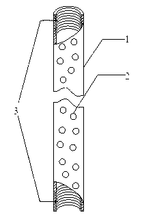
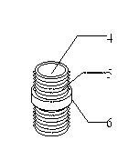
[0024] like figure 1 and figure 2As shown, the electroosmotic electrode of the present invention includes a segmented drainage electrode tube 7 , a flexible conductive joint 8 and a conductive filter cloth 9 . The segmented drainage electrode tube 7 is made of graphite material with excellent corrosion resistance and reasonable price. Considering the requirements for the strength and toughness of electroosmotic electrodes in engineering practice, as well as the high strength, poor toughness and plasticity of graphite materials, etc. performance, the electroosmotic electrode 7 is made into sections with a length ranging from 2 to 4 m to meet the requirements of transportation and construction. At the same time, the sectioned drainage electrode tube 7 is coated with graphite electrode antioxidant 1 to further improve the electrode quality. corrosion resistance...


PUM

PropertyMeasurementUnit
The inside diameter ofaaaaaaaaaa
Lengthaaaaaaaaaa

Abstract

The invention discloses an electroosmosis electrode and an electroosmosis draining system thereof, which comprise sectional draining electrode pipes, conductive filter cloth, a programmable direct current power supply, a draining pipe, a timing controller, a cable, a vacuum pump, a region optimizing device and a seismic wave real-time monitoring alarm, wherein the sectional draining electrode pipes are in thread connection by soft conductive connectors, are wrapped by the conductive filter cloth on the outside, meet the requirements of construction environments on mechanical properties and corrosion resistant property, and can still be used for a long time after multiple times of earthquakes and electroosmosis, and the use efficiency of electroosmosis equipment during soft base treatment can be improved by the uninterruptible electrifying of an electroosmosis instrument, thus reducing the construction cost. Excess pore water pressure generated by earthquake action can be timely discharged from a draining channel by the electroosmosis and vacuum negative actions, thus avoiding the shock damage to upper-part soil body and the earthquake liquefaction of a liquefied soil layer caused by the excess pore water pressure. The electroosmosis electrode and the electroosmosis draining system thereof are simple in structure, convenient to construct, durable and practical, and provides technical support and guarantee for promotion and application of an electroosmosis method on the fields such as soft base reinforcing and earthquake fortification of buildings.

Description

technical field [0001] The invention relates to a foundation treatment equipment and its auxiliary system, in particular to an electroosmosis electrode and an electroosmosis drainage system required for the application of the electroosmosis method in soft clay foundation treatment and building anti-seismic anti-liquefaction. Background technique [0002] Electroosmosis is a foundation treatment method that passes direct current at both ends of the soil to make the soil complete infiltration and drainage in a short period of time and gradually consolidate. Since L. Casagrand successfully applied the electroosmotic drainage method to railway excavation engineering for the first time in 1939, scholars from various countries have carried out a lot of research work on its reinforcement mechanism and application. Existing research results have shown that in clay, silt or silty soil with a small permeability coefficient and mainly clay, electroosmosis can effectively discharge part...

Claims


Application Information

Patent Timeline
IPC IPC(8): E02D3/11
Inventor 陶明安沈扬励彦德高庄平徐海东吕若冰
Owner HOHAI UNIV
Why Eureka
Try Eureka