Battery protective circuit with single charge-discharge power tube

A technology for protecting circuits and batteries, applied in the direction of emergency protection circuit devices, electrical components, etc., can solve the problems of not prolonging the working time of the powered system, reducing working time, and loss of efficiency of the booster circuit, so as to increase available energy and prolong The effect of working time and standby time

Active Publication Date: 2013-07-24
WUXI ZGMICRO ELECTRONICS CO LTD
View PDF3 Cites 0 Cited by
  • Summary
  • Abstract
  • Description
  • Claims
  • Application Information

AI Technical Summary

Problems solved by technology

exist figure 1 In the lithium battery shown, if the boost circuit is simply connected in series with the input terminal of the power management chip 120, although the powered circuit 130 can use the energy of the cell voltage between 2.7V and 3.4V, the effect is relatively sm

Method used


Image

  • Battery protective circuit with single charge-discharge power tube
  • Battery protective circuit with single charge-discharge power tube
  • Battery protective circuit with single charge-discharge power tube

Examples


Example Embodiment

[0023] In order to make the above objectives, features and advantages of the present invention more obvious and understandable, the present invention will be further described in detail below with reference to the accompanying drawings and specific embodiments.

[0024] The "one embodiment" or "embodiment" referred to herein refers to a specific feature, structure, or characteristic that can be included in at least one implementation of the present invention. The appearances of "in one embodiment" in different places in this specification do not all refer to the same embodiment, nor are they separate or selectively mutually exclusive embodiments with other embodiments. Unless otherwise specified, the words connected, connected, and connected in this text indicating electrical connection all mean direct or indirect electrical connection.

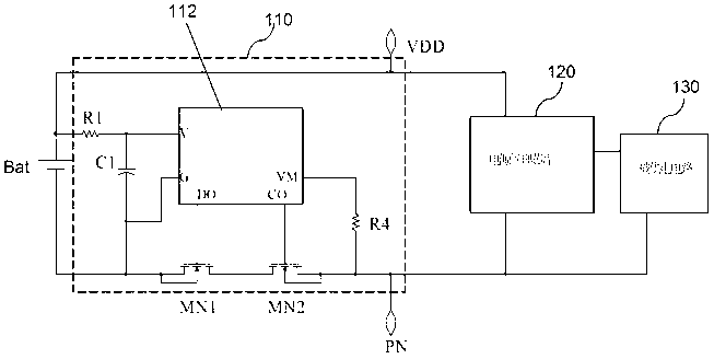
[0025] The battery protection circuit with a booster circuit in the present invention not only has the functions of charging and discharging prot...


PUM


Abstract

The invention provides a battery protective circuit with a single charge-discharge power tube. The battery protective circuit with the single charge-discharge power tube comprises a battery cell, an inductor L 1, a third p-channel metal oxide semiconductor (PMOS) transistor, an n-channel metal oxide semiconductor (NMOS) transistor MN3 and a pressure boosting-battery protective circuit. The battery cell is connected between a battery cell node and a ground node, the inductor L 1 is connected between the battery cell node and a middle node, and the PMOS transistor is connected between the middle node and a first power source end. When the voltage of the middle node is smaller than the voltage of the first power source end, a lining body end of the third PMOS transistor is controlled to be connected with the first power source end. When the voltage of the middle node is bigger than the voltage of the first power source end, the lining body end of the third PMOS transistor is controlled to be connected with the middle node. The pressure boosting-battery protective circuit controls breakover and turn-off of the NMOS transistor MN3 and the third PMOS transistor, and therefore when the voltage of the battery cell node is bigger than a discharge undervoltage threshold value and smaller than the lowest work voltage of a system, pressure boosting is carried out on the battery cell, and meanwhile charge-discharge protection can be carried out on a battery.

Description

【Technical field】 [0001] The invention relates to the field of circuit design, in particular to a battery protection circuit with a boost circuit and a single charging and discharging power tube. 【Background technique】 [0002] In the prior art, the lithium battery ensures that the cells in the battery are not under-voltage discharged, over-voltage charged, or over-current discharged through a battery protection circuit (or called a battery protection chip) installed inside it. Please refer to figure 1 As shown, it is a schematic circuit diagram of a lithium battery in the prior art when supplying power. The lithium battery includes a battery cell Bat and a battery protection circuit 110 . The battery protection circuit 110 includes a resistor R1, a capacitor C1, a battery protection control circuit 112, a resistor R4, and NMOS (N-channel Metal Oxide Semiconductor) field effect transistors MN1 and MN2. The positive pole of the battery Bat is directly connected to the firs...

Claims


Application Information

Patent Timeline
IPC IPC(8): H02H7/18
Inventor 王钊赵汗青尹航李展
Owner WUXI ZGMICRO ELECTRONICS CO LTD
Why Eureka
Try Eureka