
Differential melt-electrospinning jet head

A technology of electrospinning and melt differentiation, used in textiles and papermaking, filament/thread forming, fiber processing, etc., can solve problems such as difficult mass production, high cost, and insufficient number of filaments for industrial applications. , to achieve the effect of reducing processing difficulty, improving efficiency, and ensuring the uniformity of annular distribution.

Active Publication Date: 2013-07-31
BEIJING UNIV OF CHEM TECH
View PDF5 Cites 41 Cited by
  • Summary
  • Abstract
  • Description
  • Claims
  • Application Information

AI Technical Summary

Problems solved by technology

[0005] Naoki SHIMADA and others in Japan heated the film to an extremely low viscosity through a custom-made line laser light source to prepare a row of fibers, which increased the output of fibers based on the original point light source, but the cost was still high and the output was low, making it difficult to use in batches. Production
[0006] Michal KOMáREK and Lenka MARTINOVá from Czech Republic University proposed a slit-type spinning device, but the spinning device did not solve the problem of uniform distribution of the melt at the slit, and the number of filaments was not enough Suitable for industrial application
[0007] US patent US20090121379A1 proposes electric-assisted melt blown and hot air-assisted electrospinning, and proposes to combine the high-speed stretching of hot air and the unstable thinning effect of electric field force, and increase the jet velocity of a single filament through the effect of hot air blowing , and the effect of additional electric field force makes the fiber fineness reach about 200nm, but the nozzle used in this patent is still a single nozzle, an improvement to the single jet, and the embodiment is only for solution spinning, melt spinning only Proposed method, still has its limitations for industrial application

Method used


Image

  • Differential melt-electrospinning jet head
  • Differential melt-electrospinning jet head

Examples


Embodiment Construction

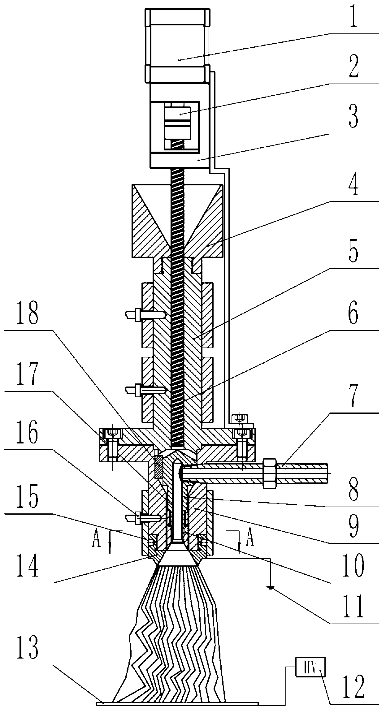
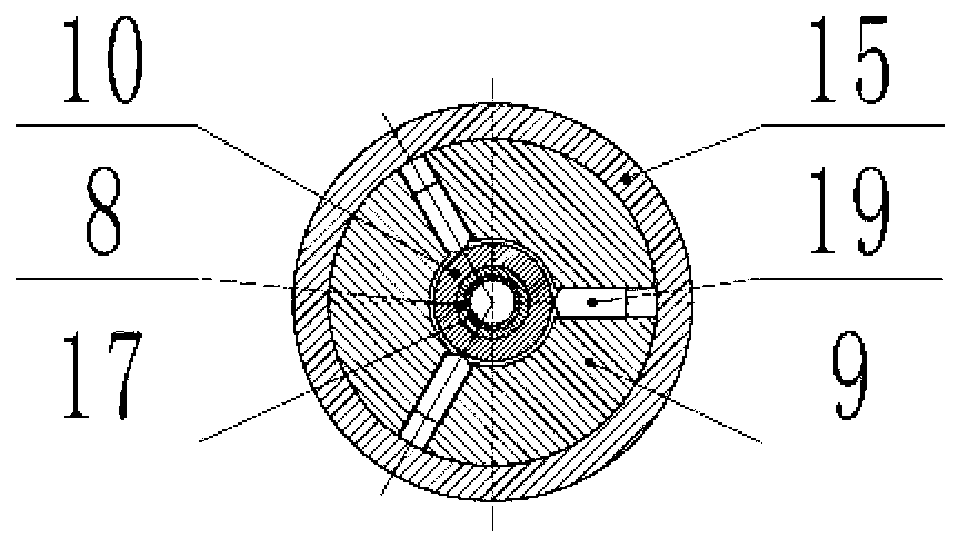
[0019] Such as figure 1 and figure 2 As shown, a melt differential electrospinning nozzle of the present invention mainly includes a hopper 4, a barrel 5, a nozzle body 9, an inner cone nozzle 14, an air inlet pipe 7, an air passage vertical pipe 8, and an air passage partition Thermal layer 17, nozzle inner body 10, key 18, top wire 19, heating device 15, temperature sensor 16, screw 6, coupling 2, servo motor 1, motor bracket 3, ground electrode 11, receiving electrode plate 13, high voltage The electrostatic generator 12, the air flow vertical pipe 8 and the nozzle inner body 10 are connected by threads, and are installed in the nozzle body 9, and the key 18 is installed between the air flow vertical pipe 8 and the nozzle body 9, so that the air flow vertical pipe 8 and the nozzle Positioning between body 9 prevents air flow channel vertical pipe 8 from rotating and misalignment. Air flow channel air inlet pipe 7 passes through nozzle body 9 and air channel vertical pipe ...


PUM


Abstract

The invention discloses a differential metl-electrospinning jet head and belongs to the field of electrostatic spinning. The differential metl-electrospinning jet head mainly comprises a hopper, a charging barrel, a jet head body, an internal cone-shaped jet head, an airflow channel air inlet pipe, an airflow channel standpipe, an airflow channel insulating layer, a jet head inner body, a button, a jackscrew, a heating device, a temperature sensor, a screw rod, a coupler, a servomotor, a motor support, a grounding electrode, a receiving electrode plate and a high-voltage electrostatic generator. The differential metl-electrospinning jet head adopts a center-feeding and side-air-intake manner, ensures uniform melt circumferential distribution through the adjustment of the jackscrew, adopts the inner cone-shaped jet head, and can spin dozens of filaments through a single jet head, thereby achieving high spinning efficiency; and by the aid of hot air, the melt layer on the inner cone surface can be blown thinner, the filaments can be drawn, and a heat insulation role can be played on the environmental temperature to slow down cooling of the filaments and prolong the filament drawing time. Therefore, the spun filaments are thinner. The differential metl-electrospinning jet head has the advantages of simple structure, capability of spinning thin fibers and high spinning efficiency.

Description

technical field [0001] The invention relates to a melt differential electrostatic spinning nozzle, which belongs to the field of electrostatic spinning. Background technique [0002] The electrospinning process is to apply a high-voltage electrostatic field between the nozzle and the receiving device, so that the polarized fluid overcomes the surface tension under the action of the electric field force, forms a jet, and obtains ultra-fine fibers on the receiving plate. [0003] With the heating up of nanotechnology, the preparation of nanofibers by electrospinning has become one of the hotspots in experimental research and industrial application. At present, most of the research on electrospinning focuses on solution electrospinning. In terms of industrialization, two routes of integration of multiple single needles and solution electrospinning without nozzles have been formed. At present, industrialization experiments are being carried out at home and abroad, but Single no...

Claims


Application Information

Patent Timeline
IPC IPC(8): D01D5/00
Inventor 杨卫民钟祥烽李好义陈宏波阎华安瑛谢鹏程焦志伟丁玉梅
Owner BEIJING UNIV OF CHEM TECH
Learn More