

stator
A stator and stator piece technology, applied in the stator field, can solve the problems of unable to suppress the vibration of the ring stator group, low rigidity, vibration and noise, etc., and achieve the effects of improving rigidity, suppressing vibration, and reducing vehicle interior sound
- Summary
- Abstract
- Description
- Claims
- Application Information
AI Technical Summary
Problems solved by technology
Method used
Image

Examples
no. 1 approach
[0043] Hereinafter, a first embodiment of the stator of the present invention will be described with reference to the drawings.
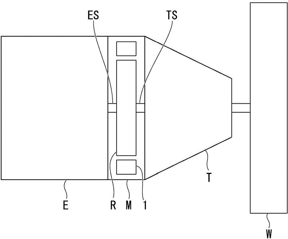
[0044] The stator of the present embodiment is used in a driving electric motor of a hybrid vehicle. Such as figure 1 As shown, the hybrid vehicle includes an internal combustion engine E (engine) and an electric motor M (rotary electrical machine) as drive sources, and the output shaft ES of the internal combustion engine E, the input shaft TS of the transmission T, and the rotor R rotating inside the stator 1 of the electric motor M link. The driving force of the internal combustion engine E and the electric motor M is transmitted to drive wheels W (wheels) via the transmission T, and the hybrid vehicle travels using the motive power of at least one of the internal combustion engine E and the electric motor M as the driving force. In addition, in this hybrid vehicle, when power is transmitted from the driving wheel W side to the motor M side du...
no. 2 approach
[0069] Next, a second embodiment of the present invention will be described based on the drawings. In this embodiment, the structure other than the reinforcement part 7 of the stator holder 3 is the same as that of the first embodiment, and therefore description thereof will be omitted.
[0070] Such as Figure 8 as well as Figure 9 As shown, the reinforcing portion 7 of the stator holder 3B of this embodiment is a plurality of convex portions 32 . The plurality of convex portions 32 ... are arranged at predetermined intervals in the circumferential direction of the peripheral wall portion 4 . Specifically, each convex portion 32 is deformed at any position in the circumferential direction of the stator holder 3B so that the corner portion formed by the peripheral wall portion 4 and the flange portion 12 protrudes radially outward. Therefore, the convex portion 32 includes a rib. Line portion 32a and side surfaces 32b, 32b.
[0071] The ridge line portion 32a is a line co...
no. 3 approach
[0080] Next, a third embodiment of the present invention will be described based on the drawings. In this embodiment, the structure other than the reinforcement part 7 of the stator holder 3 is the same as that of the first and second embodiments, and thus description thereof will be omitted.
[0081] Such as Figure 10 as well as Figure 11 As shown, the reinforcing portion 7 of the stator holder 3C of this embodiment is a convex line 33 extending continuously on the outer surface of the peripheral wall portion 4 . The protruding line 33 protrudes radially outward from a substantially central portion in the axial direction of the peripheral wall portion 4 .
[0082] Specifically, the ridge 33 has a shape in which the peripheral wall portion 4 is bent radially outward over the entire circumference at substantially the central portion of the peripheral wall portion 4 in the axial direction, and then folded radially inward at a predetermined position in the radial direction. ...
PUM
 Abstract
Description
Claims
Application Information