
Low water head vertical shaft through-flow bi-directional efficient turbine runner as well as electromechanical device and mated flow passage thereof

A water turbine, low head technology, applied in the directions of hydroelectric power generation, machine/engine, tidal flow/damless hydropower, etc., can solve problems such as shortage, and achieve the effect of high energy conversion performance, improved efficiency, and improved utilization rate

Inactive Publication Date: 2013-08-07
HOHAI UNIV
View PDF4 Cites 31 Cited by
  • Summary
  • Abstract
  • Description
  • Claims
  • Application Information

AI Technical Summary

Problems solved by technology

There are only a very small number of small-capacity units in operation for vertical shaft tubular units in my country. The main reason is the design of the flow channel of vertical shaft tubular units, the overall structural type of the unit, the connection mode of the speed increaser and the double adjustment structure. The lack of in-depth research and design of key technologies such as how to solve the arrangement of the oil receiver has resulted in this kind of shaft with simple structure, convenient installation and maintenance, excellent hydraulic performance, and low cost (20% to 60% lower than the cost of the bulb tubular unit) The tubular unit has not been developed, popularized and used

Method used


Image

  • Low water head vertical shaft through-flow bi-directional efficient turbine runner as well as electromechanical device and mated flow passage thereof
  • Low water head vertical shaft through-flow bi-directional efficient turbine runner as well as electromechanical device and mated flow passage thereof
  • Low water head vertical shaft through-flow bi-directional efficient turbine runner as well as electromechanical device and mated flow passage thereof

Examples


Embodiment

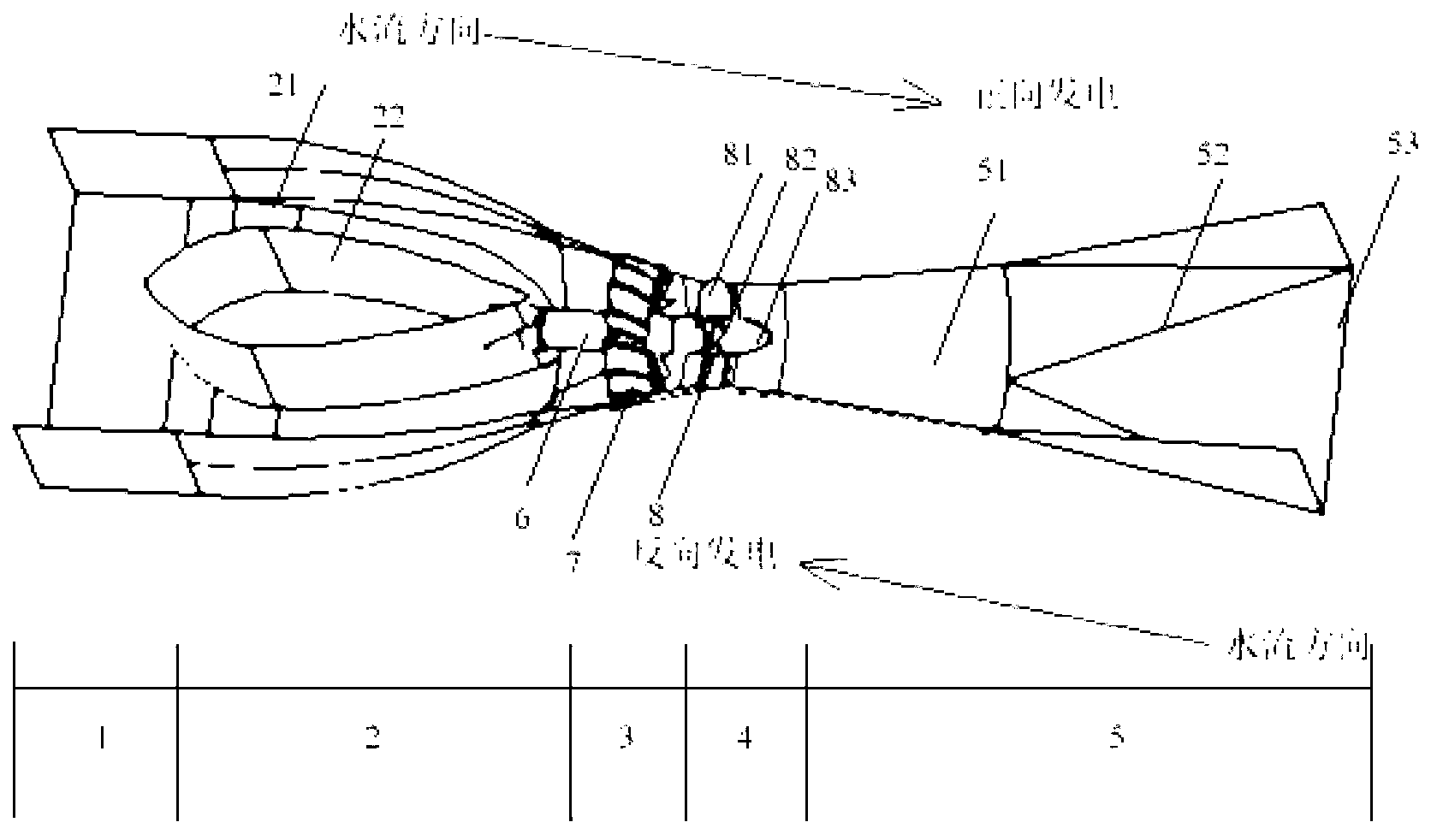
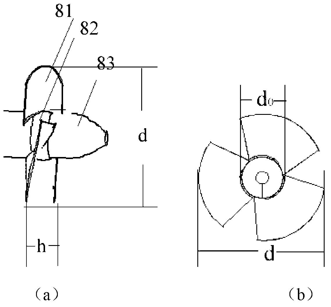
[0021] The two-way tidal power station of this embodiment is such as Figure 1-6 As shown in the figure, a low-head vertical shaft cross-flow two-way high-efficiency water turbine runner includes a runner hub and a water discharge cone. A discharge cone is installed on one side of the water discharge; the shape of the blade is thick in the middle and thin on both sides, and the ratio of the minimum thickness b1 to the maximum thickness b2 of the blade is 0.28-0.35, and the bending angle of the blade is between 90° and 95° between; the initial placement angle of the blade is 66°, and the adjustment value is at + between 3°.

[0022] The blades are three symmetrical airfoil blades arranged uniformly along the circumference of the hub of the runner.

[0023] The ratio of the runner height h to the turbine diameter d is 0.26, and the runner hub diameter d 0 The ratio to the turbine diameter d is 0.35.

[0024] The rotational speed of the runner is 200-300 rpm.

[0025] as att...


PUM


Abstract

The invention relates to a low water head vertical shaft through-flow bi-directional efficient turbine runner as well as an electromechanical device and a mated flow passage thereof. The turbine runner comprises a flow passage and an electromechanical part; the flow passage comprises a water inlet section, a vertical shaft section, a guide vane section, a runner section and a draft tube section; the electromechanical part mainly comprises an electric generator, a speed increaser, a movable guide vane, a main shaft and a water turbine; the runner comprises blades, a runner hub and a runner cone; the blades are uniformly arranged on the runner hub in the circumference direction; the section of each blade takes the shape of a symmetrical wing; the structure of the blade is that the middle part is thicker and the two ends are thinner; the ratio of the minimum thickness b1 to the maximum thickness b2 of the blade is 0.28 to 0.35; meanwhile, the wing-shaped bending angle of the blade ranges from 90 to 95 degrees; the initial placing angle of the blade is 66 degrees, and the adjusting value is within negative 3 degrees and positive 3 degrees. The turbine runner, the electromechanical device and the mated flow passage can operate bi-directionally, have better energy conversion performance, and are low in cost.

Description

technical field [0001] The invention relates to a bi-directional high-efficiency water turbine runner of a vertical shaft with low water head through flow, an electromechanical device and a supporting flow channel thereof, and belongs to the technical field of energy utilization. Background technique [0002] At present, as the high-head hydropower resources in all countries in the world are gradually exhausted, all countries are turning their attention to low-head hydropower resources, such as ocean tidal energy. After entering the 21st century, due to the impact of the sharp rise in oil prices and the pressure of carbon dioxide emission reduction, tidal energy, as a clean and renewable energy, has once again been valued by countries all over the world. Tidal power generation is the process of using the potential energy of the water level difference generated by the rising and falling tides to generate electricity, and converting the energy of seawater rising and falling ti...

Claims


Application Information

Patent Timeline
Patent Type & Authority Applications(China)
IPC IPC(8): F03B13/00F03B11/00F03B3/14F03B13/26
CPCY02E10/226Y02E10/223Y02E10/28Y02E10/20Y02E10/30
Inventor 葛新峰郑源杨春霞周大庆吴在强
Owner HOHAI UNIV
Learn More