Injection device for discharging accumulated fluids in shaft

A liquid effusion and wellbore technology, applied in jet pumps, non-displacement pumps, wellbore/well components, etc., can solve the problems of slow plunger down, limited liquid discharge, formation pollution, etc., and increase the production pressure difference , The structure of the equipment is simple, and the effect of reducing back pressure at the bottom of the well

Inactive Publication Date: 2013-08-07
XI AN JIAOTONG UNIV
View PDF5 Cites 20 Cited by
  • Summary
  • Abstract
  • Description
  • Claims
  • Application Information

AI Technical Summary

Problems solved by technology

However, in practical application of these processes, there are disadvantages such as strict scope of application, high cost, difficult operation, and difficult maintenance.
Adopting conventional drainage gas recovery methods, such as foam drainage gas recovery technology, has many advantages, but it needs to add foam drainage agent to the wellbore regularly and quantitatively. The liquid drainage capacity of the process is not high, and a large amount of foam drainage agent is invested. It also increases the cost of gas production and shortens the economically recoverable life of the gas well
However, the new technology of drainage and gas recovery, such as the ball plug gas lift process, has strong adaptability to low-pressure and low-production wells, and can adapt to complex oil and gas well conditions such as high gas-liquid ratio, sand production, high corrosion, and dee

Method used


Image

  • Injection device for discharging accumulated fluids in shaft

Examples


Embodiment Construction

[0028] The present invention will be further described in detail below in conjunction with specific embodiments, which are explanations of the present invention rather than limitations.

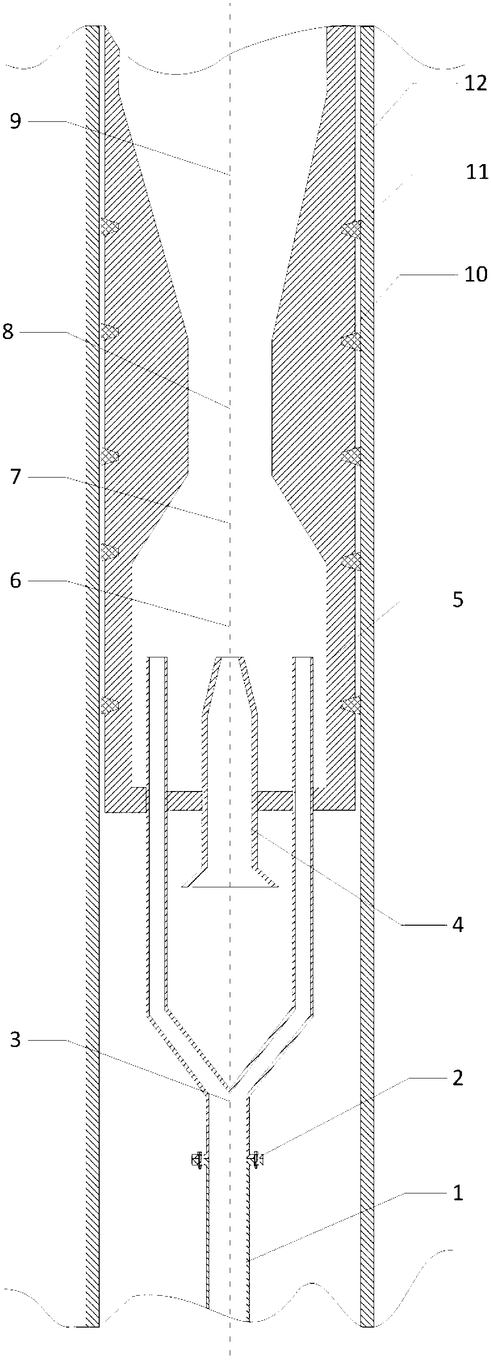
[0029] see figure 1 , an injection device for removing wellbore fluid, including a main cylinder 5 with a suction chamber 6, and the main cylinder 5 includes a suction chamber 6, a throat section 8 and a diffuser section connected in sequence from bottom to top 9. The suction chamber 6 includes a straight pipe section and a shrinkage pipe section 7, the diameter of the shrinkage pipe section 7 decreases linearly from bottom to top, and the angle between the wall line of the shrinkage pipe section 7 and the central axis of the main cylinder 5 is 45° °; the pipeline of the throat section 8 is a straight tube type; the pipe diameter of the diffuser section 9 increases linearly from bottom to top, and the dimensions of each section in the main cylinder 5 should be designed according to different ...


PUM


Abstract

The invention discloses an injection device for discharging accumulated fluids in a shaft. The injection device comprises a main shaft body with a suction chamber. A three-way pipe and a gas inlet nozzle which are inserted in the suction chamber are arranged at the bottom of the main shaft body, a plurality of sealing grooves are arranged on the periphery of the main shaft body, and each of the sealing grooves is provided with a sealing ring. High-speed jet flows are produced by high-pressure gas at an outlet of the air inlet nozzle, so that a certain vacuum degree is produced in the suction chamber, the accumulated fluids at the shaft bottom are drawn to the suction chamber under the action of inside and outside differential pressure and atomized for a certain degree in the suction chamber, flow into the throat and are fully mixed to form stable gas-liquid two-phase flow. In the process, the high-speed jet flows can transmit part of kinetic energy to the accumulated fluids, the fluid production kinetic energy is increased, and the accumulated fluids are lifted to a shaft head through a pressure diffusion section. Accordingly, the return pressure at the shaft bottom is reduced, the production differential pressure is increased, and the yield of a gas well is increased; and the high-pressure gas in the shaft is expanded due to the reduction of pressure, the instantaneous gas volume is increased, the fluid carrying capacity of the gas hole is further improved, and the accumulated fluids in the shaft are discharged.

Description

technical field [0001] The invention belongs to the technical field of multiphase flow, relates to the technical field of energy saving, and in particular relates to an ejector device for removing wellbore effusion. Background technique [0002] In the process of natural gas production, as the production time continues, the bottom hole pressure of the gas well and the natural gas flow rate gradually decrease, so that the produced water or condensate in the gas reservoir cannot be carried out of the wellbore with the natural gas flow, and thus remain in the wellbore . These liquids accumulate at the bottom of the well for a period of time, forming a liquid column, causing additional hydrostatic back pressure on the gas reservoir, resulting in a continuous decline in the self-flowing energy of the gas well. Typically, if this situation persists, the accumulated fluid column in the wellbore eventually kills the gas, shutting down the well. This phenomenon is called "fluid acc...

Claims


Application Information

Patent Timeline
IPC IPC(8): F04F5/24E21B43/00
Inventor 刘磊李晓白周芳德
Owner XI AN JIAOTONG UNIV
Why Eureka
Try Eureka