
Insertion-structure-based pilot-operated electric-hydraulic proportional spill valve

An electro-hydraulic proportional and pilot-operated technology, which is applied in the direction of fluid pressure actuators, servo motor components, mechanical equipment, etc., can solve the eccentricity of the center line of the pilot cone valve core and pilot valve sleeve, which affects the stability of hydraulic oil flow and damping Hole size can not be changed, etc., to improve the process, process formulation, processing and manufacturing convenience, and improve the effect of dynamic damping

Active Publication Date: 2013-08-07
HUAQIAO UNIVERSITY
View PDF6 Cites 9 Cited by
  • Summary
  • Abstract
  • Description
  • Claims
  • Application Information

AI Technical Summary

Problems solved by technology

[0003] At present, the conventional pilot-operated electro-hydraulic proportional relief valve mainly adopts a plate structure, which needs to be separately designed for installing the main valve sleeve, the main valve core and the main valve body of the oil inlet and outlet. The structure is relatively complicated, and the volume and weight are relatively large.
The damping hole (for pressure stabilization) and the valve seat hole (determining the pressure level of the proportional relief valve) of the traditional pilot valve sleeve are both on the pilot valve sleeve, which is difficult to process and has a low pass rate. unable to be changed
At the same time, the pilot valve sleeve and the pilot cone valve core are generally installed coaxially and separated on both sides, which may easily cause the center line of the pilot cone valve core and pilot valve sleeve to be eccentric.
In addition, in the existing commercially available products, including most of the leading product series of internationally renowned companies, the design of the pilot valve body is generally and a large number of deviated holes, which not only improves the process requirements, but also affects the flow of hydraulic oil. stability and increase the pressure loss of the valve itself

Method used


Image

  • Insertion-structure-based pilot-operated electric-hydraulic proportional spill valve

Examples


Embodiment Construction

[0032] Below in conjunction with accompanying drawing and specific embodiment this will be described in further detail.

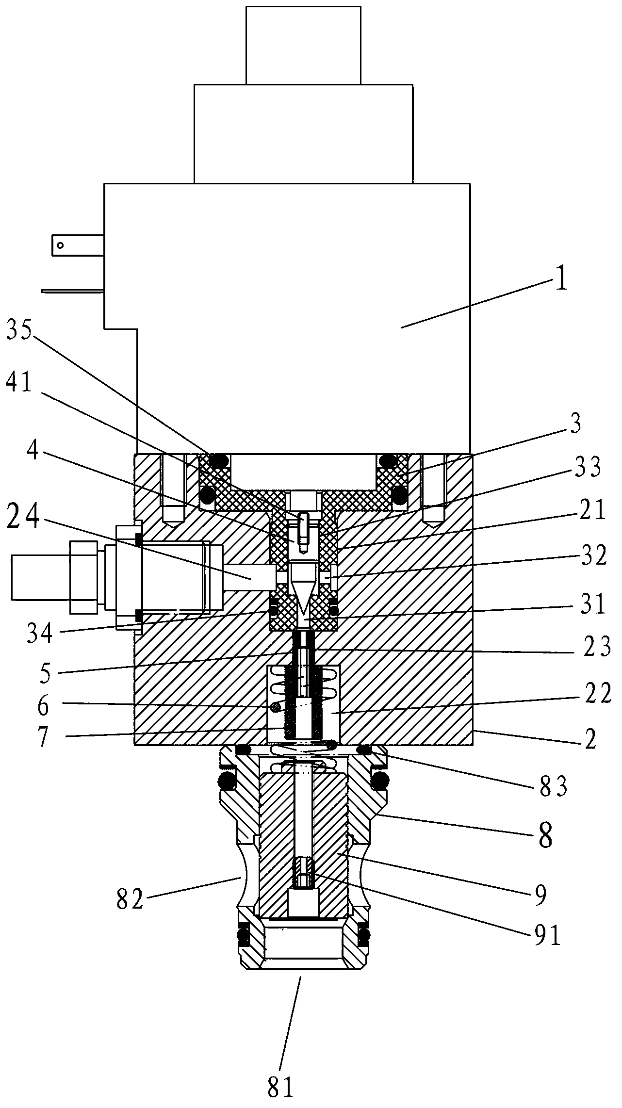
[0033] This case involves a pilot-operated electro-hydraulic proportional relief valve based on a cartridge structure, such as figure 1 As shown, it mainly includes the proportional electromagnet 1, the pilot valve body 2 and the main valve sleeve 8 arranged coaxially in sequence, and also includes the pilot valve sleeve 3, the pilot cone valve core 4, the first damper 5, the spring 6 and the main valve sleeve. Spool 9.

[0034] A first cavity 21 and a second cavity 22 are opened on both ends of the pilot valve body 2 in the axial direction, and a threaded hole 23 is formed between the first cavity 21 and the second cavity 22. The threaded hole 23 A first damper 5 is fitted inside, and an oil return port 24 is opened on the pilot valve body 2 , and the oil return port 24 is specifically extended in a radial direction and communicated with the first cavity ...


PUM


Abstract

The invention discloses an insertion-structure-based pilot-operated electric-hydraulic proportional spill valve. The spill valve comprises a proportion electromagnet, a pilot valve and a main valve sleeve. A first cavity and a second cavity are opened on the pilot valve, a threaded hole penetrates through the first cavity and the second cavity, and a first damper is arranged in the threaded hole in a fitting mode; a pilot valve sleeve is arranged in the first cavity in a sealing mode, and a pilot cone valve spool is inserted axially on the pilot valve sleeve and connected with the proportion electromagnet through a push rod; and the main valve sleeve is mounted at a cavity opening of the second cavity, a main valve spool is arranged in the main valve sleeve, and a spring abutting between the bottom of the second cavity and the main valve spool is arranged in the second cavity. By means of structural design of the spill valve, the volume and the weight of the proportional spill valve can be reduced, the valve can be adjusted easily during actual utilization, machining process requirements of parts are reduced simultaneously, and the proportional spill valve has the advantages of being simple in structure, good in manufacturability, small in flow resistance, large in through-flow capacity, fast in response, high in anti-pollution capacity and the like.

Description

technical field [0001] The invention relates to an electro-hydraulic proportional control technology and a two-way plug-in technology, in particular to a pilot-operated electro-hydraulic proportional overflow valve based on a plug-in structure. Background technique [0002] The existing domestic and foreign two-way cartridge valve products on the market, the installation hole conforms to the ISO7368 standard. The product technology is modular, configurable, open and integrated. Compared with the plate hydraulic control valve, it has obvious advantages. Proportional control and cartridge valve technology can be easily combined with the microcomputer control system, and can continuously and proportionally adjust the pressure, speed, flow, etc. of the controlled chamber, effectively improving the steady-state control accuracy and dynamic quality of the system, and fully utilizing the With the respective advantages of machine, electricity and hydraulic, the combination of two-w...

Claims


Application Information

Patent Timeline
IPC IPC(8): F15B13/02
Inventor 林添良叶月影刘强柯晓蕾
Owner HUAQIAO UNIVERSITY
Learn More