On-line monitoring system and monitoring method for distributed cable terminals

A cable terminal and monitoring system technology, applied in the field of measurement, can solve the problems that the optical fiber transmission signal scheme is not easy to achieve complete isolation of high and low potentials, the reliability of signal transmission, the measured value, and the convenience are not ideal, etc., to achieve good compatibility , Reduce power consumption, high stability effect

Active Publication Date: 2013-08-07
STATE GRID CORP OF CHINA +2
10 Cites 27 Cited by

AI-Extracted Technical Summary

Problems solved by technology

[0008] Insufficiency of existing contact temperature measurement schemes: contact temperature measurement schemes usually use thermocouples, optical fiber sensors, and resistive sensors as temperature measurement sensors. The measurement at room temperature requires cold end compensation. In actual measurement, when the distance between the hot end and the cold end is far away, a compensation wire is also required; How to install and route the fiber optic sensor is very problematic. The optical fiber transmission signal scheme is not easy to achieve complete isolation of high and low potentials. When the transmitting end is installed with a high voltage end, the problem of...

Method used

(1), the system has selected the latest nanowatt technology ultra-low power consumption microcontroller of Microchip's unique manufacturing process as the core, and its power consumption in operation and sleep state has reached a very low level;
(4), the wireless transmission module is the largest part of the power consumption in the system, under the situation of not sending data, its power supply is cut off, can not produce power consumption, has adopted on the system software to change and surpass the threshold value to go up immediately Send, otherwise send once every 8 times to minimize power consumption without affecting data update;
About ZigbBee module, there are a lot of mature commercially available products now, and common Zigbee wireless signal transmission platform is all made up of an 8-bit or 16-bit single-chip microcomputer and Zigbee radio frequency chip. With the development of chip design, a wireless single-chip microcomputer has appeared at present, which integrates the processor module and the radio frequency module in the same chip. Ti-Chipcon's CC2430 is like this. CC2430 integrates Zigbee RF front-end, ROM and 8051 microcontroller in one chip, and its size is only 7mm×7mm, which makes the equipment highly integrated, with few peripheral components and very small appearance. Small; in receiving and transmitting modes, the current consumption is lower than 27mA or 25mA respectively, and supports four sleep mechanisms, which can greatly reduce power consumption; CC2430 works in the free frequency band of 2.4GHz, and the chip price is relatively low, and the cost of use is very low Low, so CC2430 is in line with the design requirements of Zigbee wireless data signal transmission network platform.
Because the present invention adopts object-oriented design concept and distributed system architecture, the temperature of the monitoring point is monitored by the wireless temperature sensor, and the temperature data is sent to the communication gateway by wirele...

Abstract

The invention relates to an on-line monitoring system and a monitoring method for distributed cable terminals, and belongs to the measurement field. The whole system is divided into three layers from top to bottom. The bottom layer is a target layer comprising wireless temperature sensors mounted on temperature measuring points, each sensor monitors the temperature of one monitored target and transmits data to the outside through wireless methods; the middle layer is a partition layer comprising a wireless communication gateway, switch cabinet or voltage intervals can be taken as targets by the wireless communication gateway to perform configuration as required on site; the collected measuring results can be transmitted by the wireless communication gateway through various channel methods ready on site; the top layer is a station layer comprising a central server for gathering monitoring centers; and data transmitted by the wireless communication gateways can be received by the central server through various channel methods ready on site, and are displayed, stored and analyzed by the central server, so that out-of-limit warning or accident pre-warning functions can be realized. The on-line monitoring system and the monitoring method for the distributed cable terminals can be widely applied to the equipment condition monitoring field of power systems.

Application Domain

Thermometer detailsTransmission systems

Technology Topic

Condition monitoringEngineering +5

Image

  • On-line monitoring system and monitoring method for distributed cable terminals
  • On-line monitoring system and monitoring method for distributed cable terminals
  • On-line monitoring system and monitoring method for distributed cable terminals

Examples

  • Experimental program(1)

Example Embodiment

[0046] The present invention will be further described below in conjunction with the drawings.
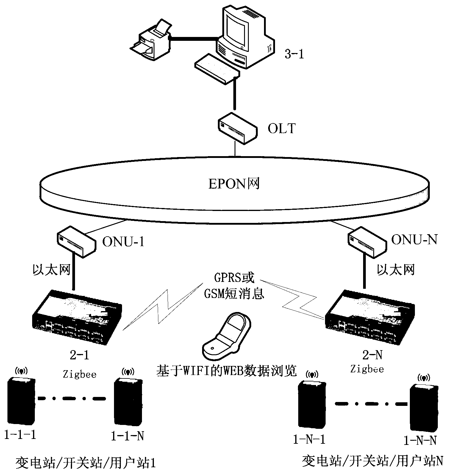
[0047] figure 1 Among them, the distributed cable terminal online monitoring system of the present invention adopts an object-oriented design idea and a distributed system architecture, and is composed of a wireless temperature sensor, a communication gateway, a transmission channel, and a central server.
[0048] Wireless temperature sensor (hereinafter referred to as temperature sensor) 1-1-1~1-NN are directly installed at the temperature monitoring point, and the temperature data is sent to the wireless communication gateway (hereinafter referred to as communication gateway) through the 2.4GHz wireless network 2- 1~2-N, because there is no direct electrical connection between the temperature sensor and the communication gateway, it will not affect the equipment insulation.
[0049] For large-scale application sites, due to the large number of sensors or the long communication distance, the large area can be divided into several relatively small areas. Each area is equipped with a communication gateway, and the monitoring points in the area are nearby. The temperature is collected.
[0050] Multiple communication gateways can be networked through their own communication interfaces, so as to collect data in one of the communication gateways to achieve centralized collection and forwarding of data.
[0051] For small-scale box transformers and user stations, because there are fewer monitoring points and relatively concentrated, a communication gateway can achieve the required functions.
[0052] Set up a central server 3-1 at the central office, which collects data from several substations, box transformers, and user stations through specific wired or wireless channels, and summarizes them to realize real-time data display, historical data storage, report generation, and historical curve , SMS alarm and other functions, and can be expanded according to user needs.
[0053] The wireless network is a 2.4GHz Zigbee wireless communication network; the measurement result includes the actual operating temperature of the cable connector or cable terminal surface.
[0054] The wireless communication gateway described is 2.4G Zigbee wireless communication gateway, which provides Zigbee wireless temperature collection interface and local maintenance function based on WIFI or RS232, realizes Ethernet communication, serial communication, GPRS communication, and WEB browsing function based on wireless WIFI And self-organizing network function.
[0055] Between the communication gateway and the central server of the centralized monitoring center, an EPON network is set up for long-distance data transmission.
[0056] The EPON network is composed of the user-side optical network unit ONU, the office-side optical line terminal OLT and the optical fiber connecting the two; the user-side optical network unit ONU is connected to the wireless communication gateway in a serial port mode or an Ethernet mode, The office-side optical line terminal OLT is connected to the central server of the centralized monitoring center in serial port mode or Ethernet mode.
[0057] In summary, the digital temperature sensor in this technical solution is placed close to the temperature measurement point of the cable terminal to sense the temperature of the point to be measured. The ultra-low power CPU collects the temperature of the temperature sensor regularly, and uses the Zigbee wireless transmitter module to wirelessly The way to send out.
[0058] The communication gateway receives the temperature signal sent by each sensor through the Zigbee wireless receiving module, and sends it out in a wired or wireless manner through a specific channel according to the communication conditions on the spot.
[0059] The central server is equipped with an industrial computer, which receives the data sent by the communication gateway through the communication port, and performs display, storage and analysis, and realizes the functions of over-limit warning and accident warning.
[0060] figure 2 Among them, the wireless temperature sensor includes a temperature sensor, a low-power single-chip computer, a wireless transmitter module and a random power supply. The temperature sensor, low-power single-chip microcomputer and wireless transmitter module are integrated on a circuit board and installed and fixed on the wireless temperature sensor housing 2- In the cavity 2-4 of 1, the random power supply is set in the battery compartment 2-5, the wireless signal transmitting antenna 2-6 of the wireless transmitting module is fixed on the upper cover 2-2, and the temperature measuring probe 2-3 of the temperature sensor is set On the bottom surface of the wireless temperature sensor, it is in close contact with the surface of the measured object.
[0061] As can be seen from the figure, the mechanical structure of the sensor housing is made of flame-retardant and high-temperature resistant PE plastic. It is composed of a housing and a cover plate. A hole is opened under the housing to expose the temperature probe.
[0062] After the circuit board of the sensor is welded and debugged, it is assembled on the bottom of the structure to ensure that the probe is exposed from the bottom of the shell. Then epoxy potting. After potting, cover the top cover, and go through the shielding and insulation treatment processes to become the final product.
[0063] image 3 Among them, the single-chip microcomputer U1 is the core of the system. It supplies power to the temperature sensor (due to its extremely low power consumption) through the IO pin, and reads the real-time temperature value of the temperature sensor through the serial bus (SPI). When the collected temperature is When the difference between the value and the last collected value is greater than the set value, the single-chip microcomputer controls the IO pin to open D1 (PMOS switch) to supply power to Z1 (Zigbee module), and transmit the temperature value via the serial bus (SPI) wirelessly To send it out.
[0064] The main chip models are as follows:
[0065] B1 is a high-performance, high-temperature-resistant lithium-ion battery;
[0066] C1 is a surface mount tantalum capacitor, used to provide large current at the moment of launch;
[0067] D1 is the PMOS switch TPS1100;
[0068] Z1 is SZ05-ZBEE series Zigbee wireless communication module;
[0069] U1 is Microchip's ultra-low power MCU PIC24F16KL402;
[0070] S1 is ADI's high precision wide range digital temperature sensor ADT7410.
[0071] The temperature sensor of this system adopts a digital temperature sensor. Because the output of the sensor is a digital signal, it is directly interfaced with the CPU through a serial bus. Compared with the sensor with analog output such as thermocouple and thermal resistance, it does not need to be verified or corrected, so it is stable. The degree is extremely high.
[0072] Zigbee technology is a short-range wireless communication technology with unified technical standards. The physical layer and media access control layer protocol is IEEE802.15.4 protocol standard, and the network layer and security layer are formulated by the Zigbee Alliance. The development of the application layer should be developed and utilized according to the needs of users.
[0073] The Zigbee device is a low-power device with a transmission output power of 0~3.6dBm, and a communication distance of usually 30~70m. It has energy detection and link quality indication capabilities. According to these detection results, the equipment can automatically adjust the transmission power to ensure Under the condition of the quality of the communication link, the equipment energy is consumed to the minimum.
[0074] The ZigBee module is a module prepared for product development of block speed, high efficiency and stable application. It hides the components that must be connected to the ZigBee chip, as well as complex processes such as high-frequency wiring. Users do not need to know RF knowledge, and directly follow the common It can be used in the form of a chip, which greatly reduces the difficulty of hardware design of the ZigBee network.
[0075] Regarding the ZigbBee module, there are now many mature commercial products. The common Zigbee wireless signal transmission platform is composed of an 8-bit or 16-bit single-chip microcomputer and a Zigbee radio frequency chip. With the development of chip design, wireless single-chip microcomputers have emerged, that is, the processor module and the radio frequency module are integrated into the same chip. This is the case with Ti-Chipcon’s CC2430. CC2430 integrates Zigbee RF front-end, ROM and 8051 microcontroller in a single chip, and the size is only 7mm×7mm, which makes the equipment integration high, few peripheral devices, and very large appearance. Small; in the receiving and transmitting modes, the current consumption is lower than 27mA or 25mA, and supports four sleep mechanisms, which can greatly reduce power consumption; CC2430 works in the 2.4GHz free frequency band, and the chip price is relatively low, and the use cost is very high Low, so CC2430 is in line with the design requirements of Zigbee wireless data signal transmission network platform.
[0076] When the transmitting/receiving communication distance is relatively short, a low-cost, low-energy RF receiving/sending chip such as CC1100 from Chipncon AS can also be used.
[0077] Regarding the specific working principles and application circuits of various ZigBee modules, you can refer to the product information of each chip/module manufacturer. It will also provide the standard application circuits of the respective chips and the preferred parameters of the corresponding components, so the further information is here. No longer describe.
[0078] For the specific construction of the ZigBee wireless network module, you can also refer to the relevant content in the ZigBee Module ZICM2410 Application Development Guide on "Embedded Industrial Control Network" (www.embedcontrol.com), which will not be described here.
[0079] The principle of achieving ultra-low power consumption in this technical solution is described as follows:
[0080] Since the wireless temperature sensor is powered by a lithium battery, in order to extend the battery life, an ultra-low power consumption design method is adopted in the circuit design, which mainly includes the following points:
[0081] (1) The system chooses the latest nanowatt technology ultra-low power MCU with Microchip's unique manufacturing process as the core, and its power consumption in running and sleep states has reached a very low level;
[0082] (2) Due to the high power consumption of the temperature acquisition and wireless transmission part, in the software design, the timing mechanism is adopted, and the CPU is in an ultra-low power sleep state under normal circumstances, and the power supply to the temperature sensor and wireless transmission module is cut off. , The static power consumption is lower than 0.7uA. When the timing time is up (the default time is 30 seconds), the CPU wakes up and performs temperature collection. The temperature value collected this time is compared with the previous temperature value. If the threshold value (default 0.5 degrees) is exceeded, the wireless transmitter module is turned on Part of the power supply sends data. If the threshold is not exceeded, it will be sent again for 8 times.
[0083] (3) The system selects an ultra-low-power digital temperature sensor with a typical power consumption of 7uW. The power supply is realized through the I/O pin of the CPU. It is powered only when the temperature is collected. No power is supplied at other times, so no Power consumption.
[0084] (4) The wireless transmitter module is the most power-consuming part of the system. In the case of not sending data, its power supply is cut off, and no power consumption will be generated. The system software adopts the change and the threshold to be sent immediately, otherwise Send once every 8 times to minimize power consumption without affecting data update;
[0085] (5) The lithium battery and energy storage capacitor of the system are all selected with ultra-low leakage models.
[0086] As a result of the above-mentioned series of low-power design measures, the average power consumption of the system can reach within 2uA, and the 1AH lithium battery can run for more than 8 years (the influence of the self-discharge of the lithium battery has been considered).
[0087] Figure 4 As an important part of the wireless temperature measurement system, the communication gateway plays a role in the system. It collects the temperature data sent by the on-site wireless temperature sensor in real time through 2.4G Zigbee wireless communication, and uses specific wired, wireless, Fibre Channel is forwarded to the remote monitoring center (ie, the central server). It can provide local maintenance function based on WIFI or RS232, which is convenient for on-site data viewing, system parameter setting or program upgrade.
[0088] When there are many and scattered temperature measurement points on site, multiple communication gateways can be arranged on site, and multiple gateways can be connected to each other through RS485 bus. In this case, one of them The communication gateway is the master gateway, and the others are slave gateways. The master gateway communicates with other slave gateways to collect data, summarize them, and then centrally transmit the data to the upper level through wired or wireless network communication.
[0089] The communication gateway device can choose the HLK-WIFI-M03 embedded Uart-Wifi module product of Shenzhen Hilink Electronics. Its built-in wireless network protocol IEEE802.11 protocol stack and TCP/IP protocol stack can realize the transfer of user serial data to the wireless network. Conversion between. Through this module, the communication gateway can easily access the wireless network only through the serial port. The module has built-in WEB function, and can realize wireless temperature release and browsing based on WEB browsing mode through the software setting inside the communication gateway device. On the smart terminal with WIFI function, the data can be viewed through the WEB browsing function.
[0090] In addition, the Siemens GPRS module MC55 can be extended inside the communication gateway device to realize the GSM short message function.
[0091] Figure 5 In, a network topology structure that can be cascaded between multiple gateways through the network is given, and the rest are the same Figure 4.
[0092] Image 6 In, the distributed cable terminal online monitoring system of the present invention follows an object-oriented, hierarchical and distributed design idea, and divides the entire system into three layers from bottom to top:
[0093] The lowest layer is the object layer, including wireless temperature sensors installed at various temperature measurement points; each sensor can monitor the temperature of a monitored object and transmit data wirelessly, which can be performed according to the needs of the monitoring object on site The flexible configuration of wireless temperature sensors does not affect each other.
[0094] The middle layer is the bay layer, including the wireless communication gateway; the wireless communication gateway is configured with switchgear or voltage interval as the object according to site needs, and multiple wireless communication gateways can realize cascading forwarding; The wireless communication gateway forwards the collected measurement results through various channels available on site.
[0095] The top layer is the station control layer, including the central server of the centralized monitoring center; the central server receives the data sent by the wireless communication gateways through various channels available on site, and displays, stores and analyzes the data to achieve more Limited warning or accident warning function.
[0096] In this figure and the following figures, hollow frame arrows are used to indicate fiber optic cable or light connection, solid line arrows are used to indicate network connections, and dotted arrows are used to indicate wireless network connections. This is a common usage in the industry and will not be described in detail.
[0097] Figure 7 In this, the distributed cable terminal online monitoring system adopts a distributed system architecture. The wireless temperature sensor monitors the temperature of the cable joint or the surface of the cable terminal in real time, and sends the temperature data to the wireless communication gateway and wireless communication gateway through the Zigbee wireless communication network. Collect the temperature of each monitoring point in the area nearby to realize the centralized collection and forwarding of data; a central server is set up in the centralized monitoring center, which collects the information of various substations, box transformers, and user stations through various channels available on site. Data, and summarize, realize real-time data display, historical data storage, report generation, historical curve or SMS alarm function.
[0098] The above-mentioned various channel modes available on site, including fiber channel mode, remote control channel mode or wireless channel mode;
[0099] When the fiber channel mode is adopted, the wireless communication gateway directly connects to the user-side optical network unit ONU through the network port, and the central server receives data from various substations, box transformers, and user stations through the office-side optical line terminal OLT .
[0100] When the remote control channel mode is adopted, the wireless communication gateway is connected to a remote central server through an Ethernet network port or serial port, and the central server receives various substations and box-type Data of transformers and user stations.
[0101] When the wireless channel mode is adopted, the wireless communication gateway sends data wirelessly through GPRS or GSM short messages, and the central server receives data from various substations, box transformers, and user stations in a wireless network. .
[0102] Because the present invention adopts object-oriented design ideas and distributed system architecture, the temperature of the point to be monitored is monitored by the wireless temperature sensor, and the temperature data is sent to the communication gateway through wireless communication, which solves the reliable isolation of the high voltage end and the low voltage system potential Problem: Divide the entire system into three layers from bottom to top to achieve flexible configuration without affecting each other's technical effects; it can adapt to a variety of networking methods and data transmission methods, and has good compatibility with existing data transmission networks. Reduce the cost of reconstruction of the existing data transmission network; the output of the wireless temperature sensor is a digital signal, which is directly interfaced with the CPU through the serial bus. Compared with the sensor with analog output such as thermocouple and thermal resistance, it does not need to be verified or corrected, so The stability is extremely high.
[0103] The invention can be widely used in the field of power system equipment state monitoring.

PUM

no PUM

Description & Claims & Application Information

We can also present the details of the Description, Claims and Application information to help users get a comprehensive understanding of the technical details of the patent, such as background art, summary of invention, brief description of drawings, description of embodiments, and other original content. On the other hand, users can also determine the specific scope of protection of the technology through the list of claims; as well as understand the changes in the life cycle of the technology with the presentation of the patent timeline. Login to view more.

Similar technology patents

SaaS (Software As A Service) function customization system and method based on metadata driving

InactiveCN106371832AFlexible configurationhigh maturity
Owner:石化盈科信息技术有限责任公司

Classification and recommendation of technical efficacy words

  • Reduce power consumption
  • Flexible configuration

Electrode array for use in medical stimulation and methods thereof

InactiveUS20050038489A1reduce power consumptionincrease battery life
Owner:CASE WESTERN RESERVE UNIV

Method of reselecting a cell based on priorities

ActiveUS20090181676A1ensure quality of servicereduce power consumption
Owner:LG ELECTRONICS INC

Organic light-emitting devices with mixed electron transport materials

InactiveUS20060204784A1good luminance efficiency and stabilityreduce power consumption
Owner:EASTMAN KODAK CO
Why Eureka
Try Eureka