Initial cavitation threshold distribution rebuilding method based on ultrasonic active cavitation imaging

An imaging and active technology, applied in the space-time high-resolution, high-signal field of beamforming, can solve the problems of sacrificing imaging frame rate, medium transparency limitation, PCD can not provide spatial distribution information, etc., to achieve high detection sensitivity and spatial resolution. high signal-to-noise ratio

Active Publication Date: 2013-08-07
XI AN JIAOTONG UNIV
View PDF5 Cites 22 Cited by
  • Summary
  • Abstract
  • Description
  • Claims
  • Application Information

AI Technical Summary

Problems solved by technology

[0004] Active cavitation detection uses the transducer to actively emit acoustic signals to act on the target area, and reflects the cavitation state by detecting the backscattered echo of cavitation bubbles. The most basic method is B-ultrasound imaging, and the B-ultrasound imaging process determines the The quasi-real-time nature of ultra-images, that is, different scan lines of each frame of image are not obtained at the same time, and the imaging frame rate is also limited to tens of Hz, which cannot realize the acquisition of transient behavior of cavitation bubbles
The Fink group of INSERM in France proposed a plane wave composite fast ultrasonic imaging method for the detection and imaging of cavitation nucleation. This method realizes high frame rate real-time imaging through plane wave emission, and proposes ...

Method used


Image

  • Initial cavitation threshold distribution rebuilding method based on ultrasonic active cavitation imaging
  • Initial cavitation threshold distribution rebuilding method based on ultrasonic active cavitation imaging
  • Initial cavitation threshold distribution rebuilding method based on ultrasonic active cavitation imaging

Examples


Embodiment Construction

[0033] The present invention will be further described in detail below in conjunction with the accompanying drawings.

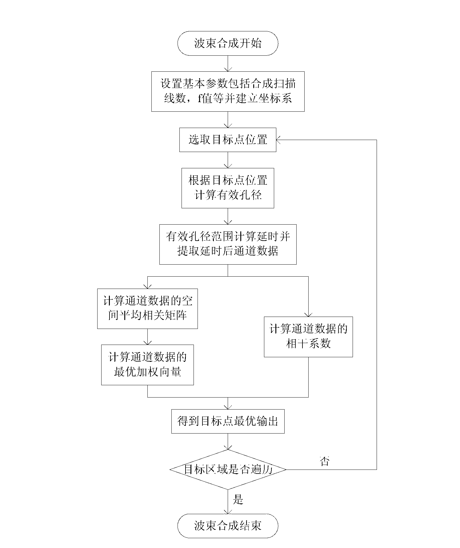
[0034] The cavitation onset threshold distribution reconstruction method based on ultrasonic active cavitation imaging includes the following steps:

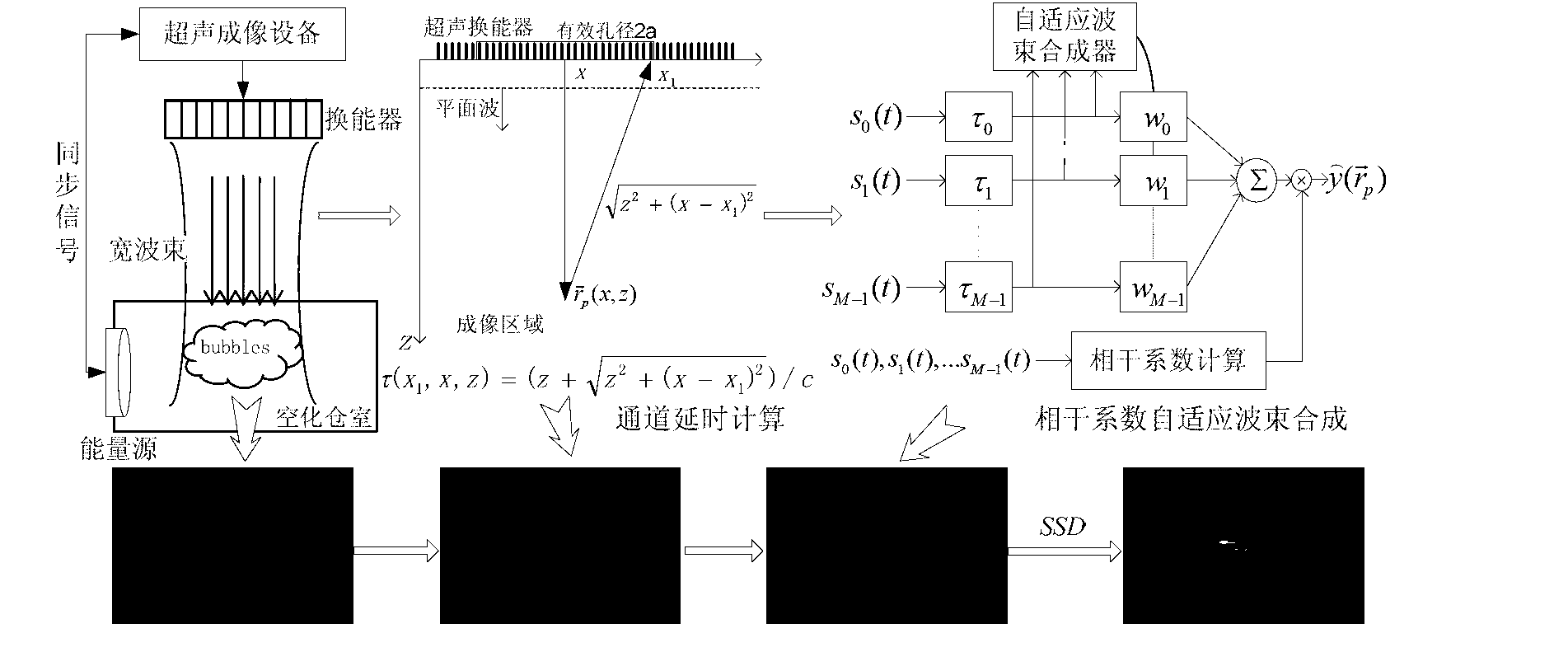
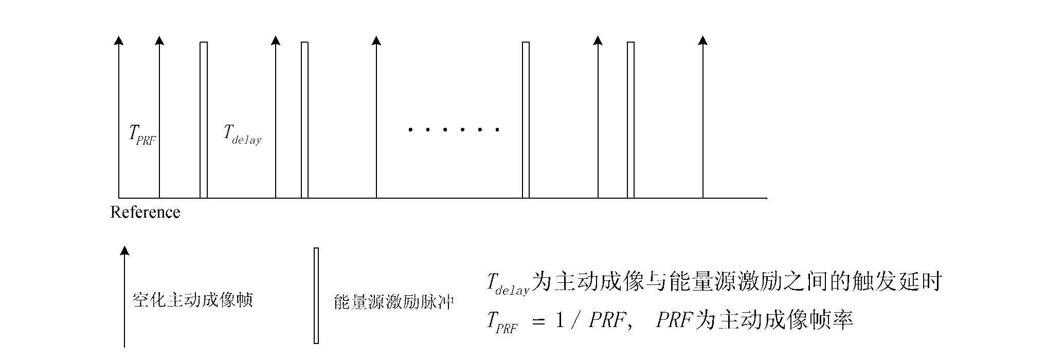
[0035] Step 1. Encouraging the generation of cavitation under the condition that the temperature or pressure of the source energy is continuously adjustable, and detecting the cavitation signal. The cavitation generation device includes a source device for generating an energy field and a synchronous signal generator for controlling timing; The cavitation signal detection device includes a programmable wide-beam high-frequency array transducer and a parallel channel data acquisition and storage unit. The synchronous signal generator generates synchronous signals to control the energy source device and the array transducer respectively. The energy source device generates The generation of cavitation is stimulate...


PUM


Abstract

The invention discloses an initial cavitation threshold distribution rebuilding method based on ultrasonic active cavitation imaging. The method comprises the steps of: firstly, emitting a synchronizing signal to a cavitation power source and a full-digitalized ultrasonic imaging device by a signal generator; stimulating a medium through continuous variable power to generate the cavitation by the power source; simultaneously emitting a plane wave and receiving a cavitation echo signal by the full-digitalized ultrasonic imaging device; achieving a cavitation bubble distribution imaging sequence with high resolution and high signal-to-noise ratio through the echo signal by synthetic aperture time delay, correlation coefficient adaptive beam synthesis and interframe decorrelation SSD (steady-state distribution); carrying out region segmentation and extracting a sub-area power intensity curve (PIC) from a sequence image; setting an intensity threshold in the PIC; taking the power corresponding to the intensity threshold as a cavitation initial threshold; and rebuilding the initial cavitation threshold space distribution by pseudo color coding after the initial threshold of each sub-area is obtained. By adopting the method disclosed by the invention, the intuitive image analysis is provided for a cavitation bubble distribution state under the effects under different powers and different parameters; and the foundation is provided for the cavitation analysis of different mediums.

Description

technical field [0001] The present invention relates to the technical field of ultrasonic detection and ultrasonic imaging, and in particular to a cavitation initiation threshold distribution reconstruction method based on ultrasonic active cavitation imaging. Based on ultrasonic active cavitation imaging with high temporal resolution and high signal-to-noise ratio, a high-frequency ultrasonic reconstruction method for spatial distribution of cavitation onset threshold is proposed. Background technique [0002] Cavitation refers to the activation of cavitation nuclei in liquids under the action of external energy (heat / force), which manifests as a series of dynamic processes such as oscillation, growth, shrinkage and even collapse of tiny nuclei. The main mechanisms of release, gene transfection, in vitro lithotripsy, thrombolysis, hemostasis, hyperthermia, and thermal ablation of tumors. The cavitation formation process is accompanied by the generation of cavitation bubble...

Claims


Application Information

Patent Timeline
IPC IPC(8): G01N29/14
Inventor 万明习胡虹王素品王晶晶
Owner XI AN JIAOTONG UNIV
Why Eureka
Try Eureka